Wednesday, 18 July 2018
Processor
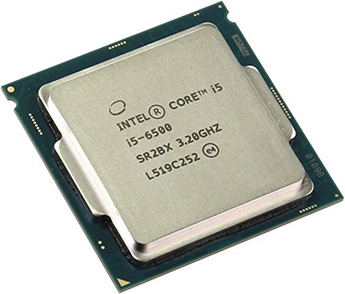
Identifying
a processor
The Microprocessor requires information to process the data.
It retrieves this information from the external memory such as RAM. This
process of retrieving the instruction from the memory is time consuming and
slows down the processing. The latest microprocessors have memory known as
Level 1 (L1) cache built into the microprocessor. Microprocessor stores
required information in this cache.
To identifying a processor you need to know following
factors:
Clock
Speed
Front Side Bus (FSB)
L2 Cache
Clock Speed:
The speed of
microprocessor depends on various factors, such as the number of instruction it
processes, the bandwidth and the clock speed. An instruction is a command that
the microprocessor executes. The clock speed specifies the speed at which the
microprocessor processes an instruction. The clock speed of the microprocessor
varies from 66MHz to 3.8 GHz.
The speed of
microprocessor also depends on the number of transistors built into the
processor. The Transistors in the microprocessor boost the data signals on the
processor. The advancement in technology has reduced the size of the
transistors and have increased the processing speed of the processor.
Front Side
Bus (FSB): FSB
refers to the bus that connects the CPU to the system memory. It is also known
as the System Bus Memory Bus. It measures the speed at which the CPU
communicates with the RAM. FSB connects the CPU to the north bridge of the
motherboard. North Bridge holds the memory controller and allows the processor to
communicate with the memory. FSB speed range from 66 to 1333 MHz. The speed of
FSB can be set up using the bios setup program or using the Jumpers on the
motherboard.
Types of
Processor:
Hyper Threading
.jpg)
Intel
Celeron

Intel
Core2Duo

Corei3
Corei5
Corei7

AMD

Troubleshooting
Processor issue:
Overheating
issue:
Check that
the processor fan is installed and functionally properly.
Ensure that
heat sink compound or thermal paste is properly in contact with the processor
and the heat sink assembly and is not dried up. If it is dried up then dab some
thermal paste on the top of processor.
Check the
Jumper settings on the motherboard and the BIOS settings to see that the
microprocessor is not over clocked. If over clocked, restore the BIOS settings
to default settings.
Slow
Processing or Hanging issue:
Clean the
system by the help of a hand blower.
Use a thin
layer of heat sink compound on the top of the processor.
Check
whether the microprocessor is compatible with the motherboard by referring to
the manual,
Check the
CPU fan whether it’s properly rotating at its recommended speed. Clean the fan.
Check the
jumper settings on the motherboard and the bios settings of the microprocessor
and change to default setting.
Check if the
microprocessor supports the applications that are running.
No
Display issue:
Check
whether the CPU fan is functioning properly.
Ensure that
the processor with heat sink assembly is properly installed.
Clear the
CMOS and check.
Check if
processor is getting core voltage. Put your index finger on top of the
processor so that you can understand whether processor is getting voltage or
not. If it is not solve then power section problem.
Tuesday, 28 March 2017
CCNA Routing
CCNA
(Cisco Certified Network Associate) is a entry level network certification now
a day’s offered by Cisco. Basically, the CCNA is developed to judge the
foundational knowledge of a candidate in networking field.
There are many streams in which a candidate can achieve the CCNA certificate, some of these are:
There are many streams in which a candidate can achieve the CCNA certificate, some of these are:
·
CCNA Cloud
·
CCNA Data Center
·
CCNA Security
·
CCNA Service Provider
·
CCNA Voice
·
CCNA Wireless
The CCNA - Routing and Switching certification is the very first step for a candidate to start his career journey in networking. Preparation for this certificate makes a candidate familiar with different basics of networking like Introduction to Networks, Routing concepts, Switching concepts, Protocol Essentials etc.
To get certified from Cisco in Routing and Switching at Associate level a candidate must need to appear in the CCNA – R&S Exam (Code- 200-120) and pass it with minimum passing criteria. The aim of this exam is to analyze a candidate's proficiency in installation, configuration, and troubleshooting for routed and switched networks.
Key points in CCNA tutorial with complete syllabus include TCP/IP, IP Addressing, Subnetting, RIP, IGRP, EIGRP, OSPF, Frame Relay, VLANs, WAN, OSI Model, Cisco Hierarchical Model, Ethernet Networking, EIGRP, VTP, DTP, NAT, Ethernet, Access Lists etc.
Use Full Link for CCNA Certification-
Use Full Link for CCNP Certification-
Use Full Link for CCIE Certification-
The OSI Model
Advantages of
Reference Models
- It
divides the network communication process into smaller and simpler
components, thus aiding component development, design, and troubleshooting.
- It
allows multiple-vendor development through standardization of network
components.
- It
encourages industry standardization by defining what functions occur at
each layer of the model.
- It
allows various types of network hardware and software to communicate.
- It
prevents changes in one layer from affecting other layers, so it does not
hamper development.
The OSI Reference Model
The OSI has seven different layers, divided into two groups. The top three layers define how the applications within the end stations will communicate with each other and with users. The bottom four layers define how data is transmitted end to end.
The OSI has seven different layers, divided into two groups. The top three layers define how the applications within the end stations will communicate with each other and with users. The bottom four layers define how data is transmitted end to end.
- Upper
Layer
APPLICATION
LAYER
|
Provides a user interface
|
PRESENTATION LAYER
|
Presents data, Handles processing such as encryption
|
SESSION LAYER
|
Keeps different applications, Data separate
|
- Lower
Layer
TRANSPORT
LAYER
|
Provides reliable or unreliable delivery, Performs error
correction before retransmit
|
NETWORK LAYER
|
Provides logical addressing, Which routers use for path
determination
|
DATA LINK LAYER
|
Combines packets into bytes and bytes into frames,
Provides access to media using MAC address, Performs error detection not
correction
|
PHYSICAL LAYER
|
Moves bits between devices, Specifies voltage, wire speed
and pin-out of cables
|
The following network devices operate at all
seven layers of the OSI model:
1. Network management
stations (NMSs)
2. Web and application servers
3. Gateways (not default gateways)
4. Network hosts
2. Web and application servers
3. Gateways (not default gateways)
4. Network hosts
The OSI reference model has seven layers:
·
The Application Layer
The Application layer of the OSI model marks the spot where users actually communicate to the computer.
The Application layer is also responsible for identifying and establishing the availability of the intended communication partner and determining whether sufficient resources for the intended communication exist. It’s important to remember that the Application layer is acting as an interface between the actual application programs.
Example, FTP and TFTP.
·
The Presentation Layer
The Presentation layer gets its name from its purpose: It presents data to the Application layer and is responsible for data translation and code formatting.
The Presentation layer gets its name from its purpose: It presents data to the Application layer and is responsible for data translation and code formatting.
·
The Session Layer
The Session layer is responsible for setting up, managing, and then tearing down sessions between Presentation layer entities. It coordinates communication between systems and serves to organize their communication
The Session layer is responsible for setting up, managing, and then tearing down sessions between Presentation layer entities. It coordinates communication between systems and serves to organize their communication
·
The Transport Layer
The Transport layer segments and reassembles data into a data stream. They provide end-to-end data transport services and can establish a logical connection between the sending host and destination host on an internetwork. Transport layer using two types of protocol TCP and UDP.
Features of TCP:
The Transport layer segments and reassembles data into a data stream. They provide end-to-end data transport services and can establish a logical connection between the sending host and destination host on an internetwork. Transport layer using two types of protocol TCP and UDP.
Features of TCP:
1.
Flow Control
Flow control prevents a sending host on one side of the connection from overflowing the buffers in the receiving host.
• The segments delivered are acknowledged back to the sender upon their reception.
• Any segments not acknowledged are retransmitted.
• Segments are sequenced back into their proper order upon arrival at their destination.
A manageable data flow is maintained in order to avoid congestion, overloading, and Data loss.
2.
Connection-Oriented Communication
In reliable transport operation, a device that wants to transmit sets up a connection-oriented communication with a remote device by creating a session. Which is called a call setup or a three- way handshake.
In reliable transport operation, a device that wants to transmit sets up a connection-oriented communication with a remote device by creating a session. Which is called a call setup or a three- way handshake.
• The first “connection
agreement” segment is a request for synchronization.
• The second and third segments acknowledge the request and establish connectionparameters
• The final segment is also an acknowledgment. It notifies the destination host that the connection agreement has been accepted and that the actual connection has been established.
A service is considered connection-oriented if it has the following characteristics:
• A virtual circuit is set up (e.g., a three-way handshake).
• It uses sequencing.
• It uses acknowledgments.
• It uses flow control. The types of flow control are buffering, windowing, and congestion avoidance.
3.
Windowing
The quantity of data segments (measured in bytes) that the transmitting machine is allowed to send without receiving an acknowledgment for them is called a windowing.
The quantity of data segments (measured in bytes) that the transmitting machine is allowed to send without receiving an acknowledgment for them is called a windowing.
4.
Acknowledgments
Reliable data delivery ensures the integrity of a stream of data sent from one machine to the other through a fully functional data link. It guarantees that the data won’t be duplicated or lost. This is achieved through something called positive acknowledgment with retransmission.
Reliable data delivery ensures the integrity of a stream of data sent from one machine to the other through a fully functional data link. It guarantees that the data won’t be duplicated or lost. This is achieved through something called positive acknowledgment with retransmission.
·
The Network Layer
The Network layer (also called layer 3) manages device addressing, tracks the location of devices on the network, and determines the best way to move data. Two types of packets are used at the Network layer: data and route updates.
The Network layer (also called layer 3) manages device addressing, tracks the location of devices on the network, and determines the best way to move data. Two types of packets are used at the Network layer: data and route updates.
1.
Data packets
Used to transport user data through the internetwork. Protocols used to support data traffic are called routed protocols; examples of routed protocols are IP and IPv6.
Used to transport user data through the internetwork. Protocols used to support data traffic are called routed protocols; examples of routed protocols are IP and IPv6.
2.
Route update packets
Used to update neighboring routers about the networks connected to all routers within the internetwork. Protocols that send route update packets are called routing protocols; examples of some common ones are RIP, RIPv2, EIGRP, and OSPF.
Used to update neighboring routers about the networks connected to all routers within the internetwork. Protocols that send route update packets are called routing protocols; examples of some common ones are RIP, RIPv2, EIGRP, and OSPF.
3.
Metric
The distance to the remote network. Different routing protocols use different ways of computing this distance.
The distance to the remote network. Different routing protocols use different ways of computing this distance.
·
The Data Link Layer
The Data Link layer provides the physical transmission of the data and handles error notification, this means that the Data Link layer will ensure that messages are delivered to the proper device on a LAN using hardware addresses. The IEEE Ethernet Data Link layer has two sub layers:
The Data Link layer provides the physical transmission of the data and handles error notification, this means that the Data Link layer will ensure that messages are delivered to the proper device on a LAN using hardware addresses. The IEEE Ethernet Data Link layer has two sub layers:
1.
Media Access Control (MAC) 802.3
Defines how packets are placed on the media. Contention media access is “first come/first served”
Defines how packets are placed on the media. Contention media access is “first come/first served”
2.
Logical Link Control (LLC) 802.2
Responsible for identifying Network layer protocols and then encapsulating them.
Responsible for identifying Network layer protocols and then encapsulating them.
Switches and Bridges at the
Data Link Layer
Layer 2 switching is considered hardware-based bridging because it uses specialized hardware called an application-specific integrated circuit (ASIC). ASICs can run up to gigabit speeds with very low latency rates. Latency is the time measured from when a frame enters a port to the time it exits a port.
Layer 2 switching is considered hardware-based bridging because it uses specialized hardware called an application-specific integrated circuit (ASIC). ASICs can run up to gigabit speeds with very low latency rates. Latency is the time measured from when a frame enters a port to the time it exits a port.
·
The Physical Layer
Physical layer does two things: It sends bits and receives bits. The Physical layer specifies the electrical, mechanical, procedural, and functional requirements for activating, maintaining, and deactivating a physical link between end systems. This layer is also where you identify the interface between the data terminal equipment (DTE) and the data communication equipment (DCE)
DCE (data circuit-terminating equipment.) The DCE is usually located at the service provider, while the DTE is the attached device.
The services available to the DTE are most often accessed via a modem or channel service unit/data service unit (CSU/DSU)
Hubs at the Physical Layer
A hub is really a multiple-port repeater. A repeater receives a digital signal and re-amplifies or Regenerates that signal and then forwards the digital signal out all active ports without looking at any data.
Ethernet Networking
Ethernet
is a contention media access method that allows all hosts on a network to share
the same bandwidth of a link.
Ethernet networking uses Carrier Sense Multiple Access with Collision Detection (CSMA/CD), A protocol that helps devices share the bandwidth evenly without having two devices transmit at the same time on the network medium. CSMA/CD was created to overcome the problem of those collisions that occur when packets are transmitted simultaneously from different nodes
Ethernet networking uses Carrier Sense Multiple Access with Collision Detection (CSMA/CD), A protocol that helps devices share the bandwidth evenly without having two devices transmit at the same time on the network medium. CSMA/CD was created to overcome the problem of those collisions that occur when packets are transmitted simultaneously from different nodes
·
Carrier
Sense Multiple Access with Collision Detection (CSMA/CD)
When a host wants to transmit over the network, it first checks for the presence of a digital signal on the wire. If all is clear (no other host is transmitting), the host will then proceed with its transmission. But it doesn’t stop there. The transmitting host constantly monitors the wire to make sure no other hosts begin transmitting. If the host detects another signal on the wire, it sends out an extended jam signal that causes all nodes on the segment to stop sending data (think busy signal). The nodes respond to that jam signal by waiting a while before attempting to transmit again. Back off algorithms determine when the colliding stations can retransmit. If collisions keep occurring after 15 tries, the nodes attempting to transmit will then timeout.
When a collision occurs on an Ethernet LAN, the following happens:
1.
A jam signal informs
all devices that a collision occurred.
2.
The collision invokes
a random back off algorithm.
3.
Each device on the
Ethernet segment stops transmitting for a short time until the timers expire.
4.
All hosts have equal
priority to transmit after the timers have expired.
The following are the effects of having a CSMA/CD network sustaining heavy collisions:
5.
Delay
6.
Low throughput
7.
Congestion
·
Ethernet
at the Data Link Layer
Ethernet at the Data Link layer is responsible for Ethernet addressing, commonly referred to as hardware addressing or MAC addressing. Ethernet is also responsible for framing packets received from the Network layer and preparing them for transmission on the local network through the Ethernet contention media access method.
Ethernet at the Data Link layer is responsible for Ethernet addressing, commonly referred to as hardware addressing or MAC addressing. Ethernet is also responsible for framing packets received from the Network layer and preparing them for transmission on the local network through the Ethernet contention media access method.
·
Ethernet
Addressing
It uses the Media Access Control (MAC) address burned into each and every Ethernet network interface card (NIC). The MAC, or hardware, address is a 48-bit (6-byte) address written in a hexadecimal format.
It uses the Media Access Control (MAC) address burned into each and every Ethernet network interface card (NIC). The MAC, or hardware, address is a 48-bit (6-byte) address written in a hexadecimal format.
Ethernet
cabling is an important discussion, especially if you are planning on taking
the Cisco exams. Three types of Ethernet cables are available:
- Straight-through cable
- Crossover cable
- Rolled cable


·
Straight-Through
Cable
The straight-through cable is used to connect Host to switch or hub, Router to switch or hub Four wires are used in straight-through cable to connect Ethernet devices. It is relatively simple to create this type, the four wires used in a straight-through Ethernet cable.
Notice that only pins 1, 2, 3, and 6 are used. Just connect 1 to 1, 2 to 2, 3 to 3, and 6 to 6 and you’ll be up and networking in no time. However, remember that this would be an Ethernet-only cable and wouldn’t work with voice, Token Ring, ISDN, and so on.
·
Crossover
Cable
The crossover cable can be used to connect Switch to switch, Hub to hub, Host to host, Hub to switch Router direct to host The same four wires are used in this cable as in the straight-through cable; we just connect different pins together. Instead of connecting 1 to 1, 2 to 2, and so on, here we connect pins 1 to 3 and 2 to 6 on each side of the cable.
The crossover cable can be used to connect Switch to switch, Hub to hub, Host to host, Hub to switch Router direct to host The same four wires are used in this cable as in the straight-through cable; we just connect different pins together. Instead of connecting 1 to 1, 2 to 2, and so on, here we connect pins 1 to 3 and 2 to 6 on each side of the cable.
·
Rolled
Cable
Although rolled cable isn’t used to connect any Ethernet connections together, you can use a rolled Ethernet cable to connect a host to a router console serial communication (com) port. If you have a Cisco router or switch, you would use this cable to connect your PC running Hyper Terminal to the Cisco hardware. Eight wires are used in this cable to connect serial devices, although not all eight are used to send information, just as in Ethernet networking.
Although rolled cable isn’t used to connect any Ethernet connections together, you can use a rolled Ethernet cable to connect a host to a router console serial communication (com) port. If you have a Cisco router or switch, you would use this cable to connect your PC running Hyper Terminal to the Cisco hardware. Eight wires are used in this cable to connect serial devices, although not all eight are used to send information, just as in Ethernet networking.
The
following are the three layers and their typical functions:
- The core layer: backbone
- The distribution layer: routing
- The access layer: switching

·
The
Core Layer
The core layer is responsible for transporting large amounts of traffic both reliably and quickly. The only purpose of the network’s core layer is to switch traffic as fast as possible.
The core layer is responsible for transporting large amounts of traffic both reliably and quickly. The only purpose of the network’s core layer is to switch traffic as fast as possible.
·
The
Distribution Layer
The distribution layer is referred to as the work-group layer and is the communication point between the access layer and the core. The primary functions of the distribution layer are to provide routing, filtering, and WAN access and to determine how packets can access the core.
The distribution layer is referred to as the work-group layer and is the communication point between the access layer and the core. The primary functions of the distribution layer are to provide routing, filtering, and WAN access and to determine how packets can access the core.
·
The
Access Layer
The access layer controls user and work-group access to internetwork resources. The access layer is referred to as the desktop layer. The network resources most users need will be available locally. The distribution layer handles any traffic for remote services.
The access layer controls user and work-group access to internetwork resources. The access layer is referred to as the desktop layer. The network resources most users need will be available locally. The distribution layer handles any traffic for remote services.

IP Adressing
It is
a numeric identifier assigned to each machine on an IP network. It designates
the specific location of a device on the network. An IP address is a software
address, not a hardware address—the latter is hard-coded on a network interface
card (NIC) and used for finding hosts on a local network. IP addressing was
designed to allow hosts on one network to communicate with a host on a
different network.
IP Terminology
IP Terminology
Bit
|
A bit is one digit,
either a 1 or a 0.
|
Byte
|
A byte is 7 or 8
bits, depending on whether parity is used.
|
Octet
|
An octet, made up of
8 bits, is just an ordinary 8-bit binary number.
|
Network address
|
This is the
designation used in routing to send packets to a remote network.
|
Broadcast address
|
The address used by
applications and hosts to send information to all nodes on a network is called
the broadcast address.
|
The Hierarchical IP Addressing Scheme
An IP address consists of 32 bits of information. These bits are divided into four sections, referred to as octets or bytes, each containing 1 byte (8 bits). You can depict an IP address using one of three methods: Dotted-decimal,
Class A: Network
. Host . Host . Host
Class B: Network . Network . Host . Host
Class C: Network . Network . Network . Host
Class D: Multicast
Class E: Research
·
Network
Address Range: Class A
The designers of the IP address scheme said that the first bit of the first byte in a Class A network address must always be off, or 0. This means a Class A address must be between 0 and 127 in the first byte, inclusive.
The designers of the IP address scheme said that the first bit of the first byte in a Class A network address must always be off, or 0. This means a Class A address must be between 0 and 127 in the first byte, inclusive.
·
Network
Address Range: Class B
Class B network is defined when the first byte is configured from 128 to 191.
Class B network is defined when the first byte is configured from 128 to 191.
·
Network
Address Range: Class C
An IP address that starts at 192 and goes to 223,
An IP address that starts at 192 and goes to 223,
·
Network
Address Ranges: Classes D and E
The addresses between 224 to 255 are reserved for Class D and E networks. Class D (224–239) is used for multicast addresses and Class E (240–255) for scientific purposes,
The addresses between 224 to 255 are reserved for Class D and E networks. Class D (224–239) is used for multicast addresses and Class E (240–255) for scientific purposes,
·
Network
Addresses: Special Purpose
Some IP addresses are reserved for special purposes, so network administrators can’t ever assign these addresses to nodes.
Some IP addresses are reserved for special purposes, so network administrators can’t ever assign these addresses to nodes.
Address
Function
Network 127.0.0.1 Reserved for loopback tests. Designates the local node and allows that node to send a test packet to itself without generating network traffic.
Node address of all 0s Interpreted to mean “network address” or any hoston specified network.
Node address of all 1s Interpreted to mean “all nodes” on the specified network; for example, 128.2.255.255 means “all nodes” on network 128.2 (Class B address).
Entire IP address set to all 0s Used by Cisco routers to designate the default route. Could also mean “any network.” Entire IP address set to all 1s (same as Broadcast to all nodes on the current network; 255.255.255.255) sometimes called an “all 1s broadcast” or limited broadcast.
Private IP Addresses
The people who created the IP addressing scheme also created what we call private IP addresses. These addresses can be used on a private network, but they’re not routable through the Internet.
This is designed for the purpose of creating a measure of well-needed security, but it also conveniently saves valuable IP address space. If every host on every network had to have real routable IP addresses, we would have run out of IP addresses to hand out years ago. But by using private IP addresses, ISPs, corporations, and home users only need a relatively tiny group of bona fide IP addresses to connect their networks to the Internet. This is economical because they can use private IP addresses on their inside networks and get along just fine.
To accomplish this task, the ISP and the corporation—the end user, no matter who they are—need to use something called Network Address Translation (NAT)
Address Class Reserved Address Space
Class A 10 . 0 . 0 . 0
through 10 . 255 . 255 . 255
Class B 172 . 16 . 0 . 0
through 172 . 31 . 255 . 255
Class C 192 . 168 . 0 . 0 through 192 . 168 . 255 . 255
CISCO
component Description
Bootstrap
Bootstrap Stored in the microcode of the ROM, the bootstrap is used to bring a router up during initialization. It will boot the router and then load the IOS.
POST
POST (power-on self-test) Stored in the microcode of the ROM, the POST is used to check the basic functionality of the router hardware and determines which interfaces are present.
ROM monitor
ROM monitor Stored in the microcode of the ROM, the ROM monitor is used for manufacturing, testing, and troubleshooting.
Mini-IOS
Mini-IOS Called the RXBOOT or boot loader by Cisco, the mini-IOS is a small IOS in ROM that can be used to bring up an interface and load a Cisco IOS into flash memory. The mini-IOS can also perform a few other maintenance operations.
RAM
RAM (random Used to hold packet buffers, ARP cache, routing tables, and also access memory) the software and data structures that allow the router to function. Running-configuration is stored in RAM, and most routers expand the IOS from flash into RAM upon boot.
ROM
ROM (read-only memory) Used to start and maintain the router. Holds the POST and the bootstrap program, as well as the mini-IOS. Flash memory Stores the Cisco IOS by default. Flash memory is not erased when the router is reloaded. It is EEPROM (electronically erasable programmable read-only memory) created by Intel.
NVRAM
NVRAM (nonvolatile RAM) Used to hold the router and switch configuration. NVRAM is noterased when the router or switch is reloaded. Does not store an IOS. The configuration register is stored in NVRAM.
Configuration register
Configuration register Used to control how the router boots up. This value can be found as the last line of the show version command output and by default is set to 0x2102, which tells the router to load the IOS from flash memory as well as to load the configuration from NVRAM.
·
Router
Boot Sequence
The Router Boot Sequence When a router boots up, it performs a series of steps, called the boot sequence, to test the hard- ware and load the necessary software. The boot sequence consists of the following steps:
The Router Boot Sequence When a router boots up, it performs a series of steps, called the boot sequence, to test the hard- ware and load the necessary software. The boot sequence consists of the following steps:
1.
The router performs a
POST. The POST tests the hardware to verify that all components of the device
are operational and present.
2.
The bootstrap then
looks for and loads the Cisco IOS software. The bootstrap is a program in ROM
that is used to execute programs. The bootstrap program is responsible for
finding where each IOS program is located and then loading the file. By
default, the IOS software is loaded from flash memory in all Cisco routers. The
default order of an IOS loading from a router is Flash, TFTP server, then ROM.
3.
The IOS software looks
for a valid configuration file stored in NVRAM. This file is called
startup-config and is only there if an administrator copies the running-config
file into NVRAM.
4.
If a startup-config
file is in NVRAM, the router will copy this file and place it in RAM and call
the file running-config. The router will use this file to run the router. The
routershould now be operational. If a startup-config file is not in NVRAM, the
router will broadcast out any interface that detects carrier detect (CD) for a
TFTP host looking for a configuration, and when that fails (typically it will
fail—most people won’t even realize the router has attempted this process), it
will start the setup mode configuration process.
·
Managing
Configuration Register
All Cisco routers have a 16-bit software register that’s written into NVRAM. By default, the configuration register is set to load the Cisco IOS from flash memory and to look for and load the startup-config file from NVRAM.
Understanding the Configuration Register Bits
The 16 bits (2 bytes) of the configuration register are read from 15 to 0, from left to right. The default configuration setting on Cisco routers is 0x2102.
Checking the Current Configuration Register Value
You can see the current value of the configuration register by using the show version command (sh version or show ver for short), as demonstrated here:
Router# sh version
The show version command will display system hardware configuration information, software version, and the names of the boot images on a router.
·
Changing
the Configuration Register
You can change the configuration register value to modify how the router boots and runs.
These are the main reasons you would want to change the configuration register:
To force the system into the ROM monitor mode to select a boot source and default boot filename.
You can change the configuration register value to modify how the router boots and runs.
These are the main reasons you would want to change the configuration register:
To force the system into the ROM monitor mode to select a boot source and default boot filename.
1.
To enable or disable
the Break function.
2.
To control broadcast
addresses.
3.
To set the console
terminal baud rate
4.
To load operating
software from ROM
5.
To enable booting from
a Trivial File Transfer Protocol (TFTP) server Before you change the
configuration register, make sure you know the current configuration register
value
You can change the configuration register by using the
config-register command.
Router (config) # config-register 0x2101
Router (config) # ^Z
Router# shver
Configuration register is 0x2102 (will be 0x2101 at next reload)
Here is our router after setting the configuration register to 0x2101 and reloading:
Router(boot)# shver
Configuration register is 0x2101 At this point, if you typed Show flash, you’d still see the IOS in flash memory ready to go.
But we told our router to load from ROM, which is why the host name shows up with (boot).
Router(boot)# sh flash
So even though we have our full IOS in flash, we changed the default loading of the router’s software by changing the configuration register. If you want to set the configuration register back to the default, just type this:
Router(boot)#config t
Router(boot)(config)# config-register 0x2102
Router(boot)(config)# ^Z
Router(boot)# reload
·
Summarization:-
Summarization, also called route aggregation, allows routing protocols to advertise many networks as one address. The purpose of this is to reduce the size of routing tables on routers to save memory, which also shortens the amount of time for IP to parse the routing table and find the path to a remote network.
Summarization, also called route aggregation, allows routing protocols to advertise many networks as one address. The purpose of this is to reduce the size of routing tables on routers to save memory, which also shortens the amount of time for IP to parse the routing table and find the path to a remote network.
·
Recovering
Passwords
If you’re locked out of a router because you forgot the password, you can change the configuration register. The default configuration register value is 0x2102, meaning that bit 6 is off. With the default setting, the router will look for and load a router configuration stored in NVRAM (startup-config). To recover a password, you need to turn on bit 6. Doing this will tell the router to ignore the NVRAM contents. The configuration register value to turn on bit 6 is 0x2142.
Password recovery steps:
1.
Boot the router and
interrupt the boot sequence by performing a break, which will takethe router
into ROM monitor mode.
2.
Change the
configuration register to turn on bit 6 (with the value 0x2142).
3.
Reload the router.
4.
Enter privileged mode.
5.
Copy the
startup-config file to running-config.
6.
Change the password.
7.
Reset the
configuration register to the default value.
8.
Save the router
configuration.
9.
Reload the router (optional).
·
Interrupting
the Router Boot Sequence
Your first step is to boot the router and perform a break. This is usually done by pressing the Ctrl+Break key combination when using HyperTerminal (personally, I use SecureCRT) whilethe router first reboots. Rommon 1 >
Notice the line monitor: command “boot” aborted due to user interrupt. At this point, you will be at the rommon 1> prompt, which is called ROM monitor mode.
Changing the Configuration Register
Change the configuration register by using the config-register command. To turn on bit 6, use the configuration register value 0x2142.
Remember that if you change the configuration register to 0x2142, the startup-config will be bypassed and the router will load into setup mode.
·
Rommon 1> prompt:
·
Rommon 1 >confreg
0x2142
·
You must reset or
power cycle for new config to take effect
·
Rommon 2 >reset
Viewing and Changing the Configuration
Now you’re past the point where you would need to enter the user-mode and privileged-mode passwords in a router. Copy the startup-config file to the running-config file:
copy startup-config running-config
Or use the shortcut: copy start run
Now you’re past the point where you would need to enter the user-mode and privileged-mode passwords in a router. Copy the startup-config file to the running-config file:
copy startup-config running-config
Or use the shortcut: copy start run
·
Backing
Up the Cisco IOS
To back up the Cisco IOS to a TFTP server, you use the copy flash tftp command. It’s a straight forward command that requires only the source filename and the IP address of the TFTP server.
The key to success in this backup routine is to make sure you’ve got good, solid connectivity to the TFTP server. Check this by pinging the TFTP device from the router console prompt like this:
Router# ping 1.1.1.2
The Packet Internet Groper (Ping) utility is used to test network connectivity,after you ping the TFTP server to make sure that IP is working, you can use the copy flash tftp command to copy the IOS to the TFTP server as shown next:
·
Router# copy flash
tftp
·
Source filename []?
·
C2800nm-advsecurityk9-mz.124-12.bin
·
Address or name of
remote host []?
·
1.1.1.2
·
Destination filename
[c2800nm-advsecurityk9-mz.124-12.bin]?
·
[Enter]
·
!!!!!!!!!!!!!!!!!!!!!!!!!!!!!!!!!!!!!!!!!!!!!!!!!!!!!!!!!!!!!!!!!!!!!!!!!!!!!!!
·
!!!!!!!
·
21710744 bytes copied
in 60.724 secs (357532 bytes/sec)
Restoring or Upgrading the Cisco Router IOS
What happens if you need to restore the Cisco IOS to flash memory to replace an original file that has been damaged or if you want to upgrade the IOS? You can download the file from a TFTP server to flash memory by using the copy tftp flash command. This command requires the IP address of the TFTP host and the name of the file you want to download.But before you begin, make sure the file you want to place in flash memory is in the default TFTP directory on your host. When you issue the command, TFTP won’t ask you where the file is, so if the file you want to use isn’t in the default directory of the TFTP host, this just won’t work.
Router# copy tftp flash
Address or name of remote host []?
1.1.1.2
Source filename []?
C2800nm-advsecurityk9-mz.124-12.bin
Destination filename [c2800nm-advsecurityk9-mz.124-12.bin]?
[Enter]
%Warning:There is a file already existing with this name
Do you want to over write? [Confirm]
[Enter]
Accessing tftp://1.1.1.2/c2800nm-advsecurityk9-mz.124-12.bin...
Loading c2800nm-advsecurityk9-mz.124-12.bin from 1.1.1.2 (via
FastEthernet0/0):
!!!!!!!!!!!!!!!!!!!!!!!!!!!!!!!!!!!!!!!!!!!!!!!!!!!!!!!!!!!!!!!!!!!!!!!!!!!!!
[OK - 21710744 bytes]
21710744 bytes copied in 82.880 secs (261954 bytes/sec)
Router#
·
Gathering
Neighbor Information
The show cdp neighbor command (shcdpnei for short) delivers information about directly connected devices. It’s important to remember that CDP packets aren’t passed through a Cisco switch and that you only see what’s directly attached. So this means that if your router is connected to a switch, you won’t see any of the devices hooked up to that switch.
The show cdp neighbor command (shcdpnei for short) delivers information about directly connected devices. It’s important to remember that CDP packets aren’t passed through a Cisco switch and that you only see what’s directly attached. So this means that if your router is connected to a switch, you won’t see any of the devices hooked up to that switch.
·
Corp# shcdp neighbors
·
Corp# shcdp neighbors
detail
Cisco Internetwork Operating System (IOS)
The
Cisco Internetwork Operating System (IOS):- is the kernel of Cisco routers and most
switches. The Cisco IOS is a proprietary kernel that provides routing,
switching, internetworking, and tele-communications features. These are some
important things that the Cisco router IOS software is responsible for:
1. Carrying network protocols and functions
2. Connecting high-speed traffic between devices
Adding security to control access and stop unauthorized network use providing scalability for ease of network growth and redundancy Supplying network reliability for connecting to network resources.
We can access the Cisco IOS through the console port of a router, from a modem into the auxiliary (or Aux) port, or even through Telnet.
Connecting to a Cisco Router
We can connect to a Cisco router to configure it, verify its configuration, and check statistics. There are different ways to do this, the first place you would connect to is the console port. The console port is usually an RJ-45 (8-pin modular) connection located at the back of the router. You can also connect to a Cisco router through an auxiliary port—which is really the same thing as a console port, the third way to connect to a Cisco router is in-band, through the program Telnet.
Bringing Up a Router
When you first bring up a Cisco router, it will run a power-on self-test (POST). If it passes, it will then look for and load the Cisco IOS from flash memory—if an IOS file is present. After that, the IOS loads and looks for a valid configuration—the startup-config—that’s stored in nonvolatile RAM, or NVRAM.
·
Router
Modes:-
Entering the CLI from a Non-ISR Router
After the interface status messages appear and you press Enter, the Router> prompt will appear. This is called user exec mode (user mode), and it’s mostly used to view statistics, But it’s also a stepping stone to logging in to privileged mode. We can only view and change the configuration of a Cisco router in privileged exec mode (privileged mode), which you can enter with the enable command. Here’s how:
Router>enable
Router#
We now end up with a Router# prompt, which indicates that you’re in Privileged mode, where you can both view and change the router’s configuration. We can go back from privileged mode into user mode by using the disable command, as seen here:
Router# disable
Router>
At this point, you can type logout
from either mode to exit the console: Router>logout
Overview of Router Modes
To configure from a CLI, you can make global changes to the router by typing configure terminal (or config t for short), which puts you in global configuration mode and changes what’s known as the running-config. A global command (a command run from global config) is set only once and affects the entire router. We can type config from the privileged-mode prompt and then just press Enter to take the default of terminal, as seen here:
Router# config
Configuring from terminal, memory, or network [terminal]? [ press enter ] Here are some of the other options under the configure command:
Router (config) # exit
or press
Cntl-z
Router# config?
Confirm Confirm replacement of running-config with a new config file
Memory Configure from NV memory
Network Configure from a TFTP network host
Overwrite-network Overwrite NV memory from TFTP network host
Replace Replace the running-config with a new config file
Terminal Configure from the terminal
Interfaces
To make changes to an interface, you use the interface command from global configuration mode:
Router (config) # interface?
·
Async Async interface
·
BVI Bridge-Group
Virtual Interface
·
CDMA-Ix CDMA Ix interface
·
CTunnel CTunnel interface
·
Dialer Dialer interface
·
FastEthernet FastEthernet IEEE 802.3
·
Group-Async Async Group interface
·
Lex Lex interface
·
Loopback Loopback interface
·
MFR Multilink Frame Relay
bundle interface
·
Multilink Multilink-group
interface
·
Null Null
interface
·
Port-channel Ethernet Channel of interfaces
·
Serial Serial
·
Tunnel Tunnel interface
·
Vif PGM Multicast
Host interface
·
Virtual-PPP Virtual PPP interface
·
Virtual-Template Virtual Template interface
·
Virtual-TokenRing Virtual Token Ring
·
Range interface range command
Router (config) # interface
fastEthernet 0/0
Router (config-if) #
Did you notice that the prompt changed to Router (config-if) #? This tells us that we’re in interface configuration mode. And wouldn’t it be nice if the prompt also gave us an indication of what interface you were configuring? Well, at least for now we’ll have to live without the prompt information, because it doesn’t. One thing is for sure: You really have to pay attention when configuring a router!
·
Gathering
Basic Routing Information
The show version command will provide basic configuration for the system hardware as well as the software version and the boot images. Here’s an example:
Router# show version
Cisco IOS Software, 2800 Software (C2800NM-ADVSECURITYK9-M), Version 12.4(12), RELEASE SOFTWARE (fc1)
The show version command will provide basic configuration for the system hardware as well as the software version and the boot images. Here’s an example:
Router# show version
Cisco IOS Software, 2800 Software (C2800NM-ADVSECURITYK9-M), Version 12.4(12), RELEASE SOFTWARE (fc1)
·
Administrative
Function
The administrative functions that you can configure on a router and switch are Hostnames, Banners, Passwords and Interface descriptions.
Remember, none of these will make your routers or switches work better or faster, but we just take the time to set these configurations on each of your network devices. That’s because doing this makes troubleshooting and maintaining your network so much easier.
1.
Hostnames
We can set the identity of the router with the hostname command. This is only locally significant, which means that it has no bearing on how the router performs name lookups or how the router works on the internetwork.
Here’s an example:
We can set the identity of the router with the hostname command. This is only locally significant, which means that it has no bearing on how the router performs name lookups or how the router works on the internetwork.
Here’s an example:
2.
Router # config t
3.
Router (config) #
hostname Todd
4.
Todd (config) #
hostname Atlanta
5.
Atlanta (config) #
hostname Todd
6.
Todd (config) #
7.
Banners
A Banner is more than just a little cool—one very good reason for having a banner is to give any and all who dare attempt to telnet or dial into our internetwork a little security notice. And we can create a banner to give anyone who shows up on the router exactly the information we want them to have.login banner, and message of the day banner (all illustrated in the following code):
A Banner is more than just a little cool—one very good reason for having a banner is to give any and all who dare attempt to telnet or dial into our internetwork a little security notice. And we can create a banner to give anyone who shows up on the router exactly the information we want them to have.login banner, and message of the day banner (all illustrated in the following code):
8.
Router (config) #
banner?
9.
login Set login banner
10.
motd Set Message of the Day banner
Message of the day (MOTD) is the most extensively used banner. It gives a message to every person dialing into or connecting to the router via Telnet or an auxiliary port, or even through a console port as seen here:
Router (config) # banner motd?
LINE c banner-text c, where ‘c’ is a delimiting character
Router (config) # banner motd #
Enter TEXT message. End with the character ‘#’.$ Acme.com
network, then you must disconnect immediately. #
Router (config) # ^Z
Router #
or
Router (config) # banner motd x Unauthorized access prohibited!
x
Login banner
We can configure a login banner to be displayed on all connected terminals. This banner is displayed after the MOTD banner but before the login prompts. The login banner can’t be disabled on a per-line basis, so to globally disable it, you’ve got to delete it with the no banner login command.
11.
Setting
Passwords
Five passwords are used to secure your Cisco routers: console, auxiliary, telnet (VTY), enable password, and enable secret. The enable secret and enable password are used to set the password that’s used to secure privileged mode. This will prompt a user for a password when the enable command is used. The other three are used to configure a password when user mode is accessed through the console port, through the auxiliary port, or via Telnet.
Enable Passwords
We set the enable passwords from global configuration mode like this:
Router (config) # enable?
12.
password Assign the privileged level password
secret Assign
the privileged level secret
The following points describe the enable password parameters:
Router (config) # enable secret Todd
Router (config) # enable password Todd
The enable password you have chosen is the same as your enable secret. This is not recommended. Re-enter the enable password. If we try to set the enable secret and enable passwords the same, the router will give you a nice, polite warning to change the second password. If you don’t have older legacy routers, don’t even bother to use the enable password.
User-mode passwords are assigned by using the line command:
Router (config) # line?
<0-337> First Line number
aux Auxiliary line
console Primary terminal
line
tty Terminal
controller
vty Virtual terminal
x/y Slot/Port for
Modems
x/y/z Slot/Subslot/Port
for Modems
Here are the lines to be concerned with:
aux
Sets the user-mode password for the auxiliary port. It’s usually used for attaching a modem to the router, but it can be used as a console as well.
console
Sets a console user-mode password.
vty
Sets a Telnet password on the router. If this password isn’t set, then Telnet can’t be used by default. To configure the user-mode passwords, you configure the line you want and use either the login or no login command to tell the router to prompt for authentication. The next sections will provide a line-by-line example of the configuration of each line configuration
Auxiliary Password
To configure the auxiliary password, go into global configuration mode and type
line aux ?
We can see here that you only get a choice of 0–0 (that’s because there’s only one port):
Router# config t
Router (config) # line aux 0
Router (config-line) password cisco
Router (config-line) # login
Router (config-line) # exit
Console Password To set the console password, use the line console 0 command.
Router# config t
Router (config) # line consol 0
Router (config-line) password cisco
Router (config-line) # login
Router (config-line) # exit
Telnet Password
Router# config t
Router (config) # line vty 0 1180
Router (config-line) # password telnet
Router (config-line) # login
Encrypting Your Passwords
Because only the enable secret password is encrypted by default, you’ll need to manually configure the user-mode and enable passwords for encryption. To manually encrypt your passwords, use the service password-encryption command.
Router# config t
Router (config) # service password-encryption
Router (config) # exit
Router # sh run
Router # config t
Router (config) # no service password-encryption
Router (config) # ^Z
·
Setting
Up Secure Shell (SSH)
Instead of Telnet, you can use Secure Shell, which creates a more secure session than the Telnet application that uses an unencrypted data stream. Secure Shell (SSH) uses encrypted keys to send data so that your username and password are not sent in the clear. Here are the steps to setting up SSH:
Instead of Telnet, you can use Secure Shell, which creates a more secure session than the Telnet application that uses an unencrypted data stream. Secure Shell (SSH) uses encrypted keys to send data so that your username and password are not sent in the clear. Here are the steps to setting up SSH:
·
Configuring
an IP Address on an Interface
Even though we don’t have to use IP on your routers, it’s most often what people actually do use. To configure IP addresses on an interface, use the ip address command from interface configuration mode:
Router (config) #int f0/1
Router (config-if) # ip address 172.16.10.2 255.255.255.0
Don’t forget to enable the interface with the no shutdown command. If you want to add a second subnet address to an interface, you have to use the secondary parameter. If we type another IP address and press Enter, it will replace the existing IP address and mask. This is definitely a most excellent feature of the Cisco IOS.
·
Router (config-if) #ip
address 172.16.20.2 255.255.255.0?
·
secondary Make this IP address a secondary address
·
< cr >
·
Router (config-if) #
ip address 172.16.20.2 255.255.255.0 secondary
·
Router (config-if) #
^Z
Router (config-if) # do sh run
Basic IP Routing
Routing
is used for taking a packet from one device and sending it through the network
to another device on a different network. Routers don’t really care about hosts
they only care about networks and the best path to each network. The logical
network address of the destination host is used to get packets to a network
through a routed network, and then the hardware address of the host is used to
deliver the packet from a router to the correct destination host.
If your network has no routers, then it should be apparent that you are not routing. Routers route traffic to all the networks in your internetwork.
To be able to route packets, a router must know, at a minimum, the following:
If your network has no routers, then it should be apparent that you are not routing. Routers route traffic to all the networks in your internetwork.
To be able to route packets, a router must know, at a minimum, the following:
- Destination address
- Neighbor routers from which it
can learn about remote networks
- Possible routes to all remote
networks
- The best route to each remote
network
- How to maintain and verify
routing information
- The router learns about remote
networks from neighbor routers or from an administrator.
The router then builds a routing table (a map of the internetwork) that describes how to find the remote networks.
Static Routing
It is used, the administrator is responsible for updating all changes by hand into all routers. Typically, in a large network, a combination of both dynamic and static routing is used.
Dynamic Routing
A protocol on one router communicates with the same protocol running on neighbor routers. The routers then update each other about all the networks they know about and place this information into the routing table. If a change occurs in the network, the dynamic routing protocols automatically inform all routers about the event.
Routing Protocol Basics:-
·
Administrative
Distances:-
The administrative distance (AD) is used to rate the trustworthiness of routing information received on a router from a neighbor router. An administrative distance is an integer from 0 to 255, where 0 is the most trusted and 255 means no traffic will be passed via this route.
If a router receives two updates listing the same remote network, the first thing the router checks is the AD. If one of the advertised routes has a lower AD than the other, then the route with the lowest AD will be placed in the routing table.
If both advertised routes to the same network have the same AD, then routing protocol metrics (such as hop count or bandwidth of the lines) will be used to find the best path to the remote network. The advertised route with the lowest metric will be placed in the routing table. But if both advertised routes have the same AD as well as the same metrics, then the routing protocol will load-balance to the remote network (which means that it sends packets down each link).
The default administrative distances that a Cisco router uses to decide which route to take to a remote network.
Default Administrative Distances
Route Source
|
Default AD
|
Connected interface
|
0
|
Static route
|
1
|
EIGRP
|
90
|
IGRP
|
100
|
OSPF
|
110
|
RIP
|
120
|
External EIGRP
|
170
|
Unknown
|
255 (this route will never be
used)
|
·
Routing
Protocols
There are three classes of routing protocols:
Distance vector:-The distance-vector protocols find the best path to a remote network by judging distance. Each time a packet goes through a router, that’s called a hop. The route with the least number of hops to the network is determined to be the best route. The vector indicates the direction to the remote network. Both RIP and IGRP are distance-vector routing protocols. They send the entire routing table to directly connected neighbors.
Link state:-In link-state protocols, also called shortest-path-first protocols, the routers each create three separate tables. One of these tables keeps track of directly attached neighbors, one determines the topology of the entire internetwork, and one is used as the routing table. Link-state routers know more about the internetwork than any distance vector routing protocol. OSPF is an IP routing protocol that is completely link state. Link state protocols send updates containing the state of their own links to all other routers on the network.
Hybrid:-Hybrid protocols use aspects of both distance vector and link state for example, EIGRP.
Static
Routing
Static
routing occurs when you manually add routes in each router’s routing table.
There are pros and cons to static routing, but that’s true for all routing
processes.
Static routing has the following benefits:
Static routing has the following benefits:
·
There is no overhead
on the router CPU, which means you could possibly buy a cheaper router than you
would use if you were using dynamic routing.
·
There is no bandwidth
usage between routers, which means you could possibly save money on WAN links.
·
It adds security
because the administrator can choose to allow routing access to certain
networks only.
Static
routing has the following disadvantages:
·
The administrator must
really understand the internetwork and how each router is connected in order to
configure routes correctly.
·
If a network is added
to the internetwork, the administrator has to add a route to it on all routers
by hand.
·
It’s not feasible in
large networks because maintaining it would be a full-time job in itself.
the
command syntax you use to add a static route to a routing table:
ip route [ destination_network] [ mask ] [ next-hop_address or exit interface ]
This list describes each command in the string:
ip route:-The command used to create the static route.
destination_network:-The network you’re placing in the routing table.
Mask:-The subnet mask being used on the network.
next-hop_address:-The address of the next-hop router that will receive the packet and forward it to the remote network. This is a router interface that’s on a directly connected network. You must be able to ping the router interface before you add the route. If you type in the wrong next-hop address or the interface to that router is down, the static route will show up in the router’s configuration but not in the routing table.
Exit interface :-Used in place of the next-hop address if you want, and shows up as a directly connected route.
Router (config) # ip route 172.16.3.0 255.255.255.0 192.168.2.4
The ip route command tells us simply that it is a static route.
172.16.3.0 is the remote network we want to send packets to.
255.255.255.0 is the mask of the remote network.
192.168.2.4 is the next hop, or router, we will send packets to.
Or
Router (config) # ip route 172.16.3.0 255.255.255.0 s0/0/0
Default routing
It is used to send packets with a remote destination network not in the routing table to the next-hop router. You should only use default routing on stub networks—those with only one exit path out of the network.
To configure a default route, you use wildcards in the network address and mask locations of a static route
Router (config) # ip route 0.0.0.0 0.0.0.0 10.1.11.1
RIP
Distance-Vector
Routing Protocols (RIP)
The distance-vector routing algorithm passes complete routing table contents to neighboring routers, which then combine the received routing table entries with their own routing tables to complete the router’s routing table. This is called routing by rumor, because a router receiving an update from a neighbor router believes the information about remote networks without actually finding out for itself. It’s possible to have a network that has multiple links to the same remote network, and if that’s the case, the administrative distance of each received update is checked first. If the AD is the same, the protocol will have to use other metrics to determine the best path to use to that remote network. RIP uses only hop count to determine the best path to a network. If RIP finds more than one link with the same hop count to the same remote network, it will automatically perform a round-robin load balancing. RIP can perform load balancing for up to six equal-cost links (four by default).
For avoiding routing Loops in (RIP)
·
Maximum
Hop Count:- RIP permits a
hop count of up to 15, so anything that requires 16 hops is deemed unreachable.
·
Split
Horizon This reduces
incorrect routing information and routing overhead in a distance-vector network
by enforcing the rule that routing information cannot be sent back in the
direction from which it was received.
·
Route
Poisoning When Network
goes down, Router initiates route poisoning by advertising Network as 16, or
unreachable.
·
Holddowns
It is the time a router think that a route is up without receiving an update about that root.
RIP is a true distance-vector routing protocol. RIP sends the complete routing table out to all active interfaces every 30 seconds. RIP only uses hop count to determine the best way to a remote network, but it has a maximum allowable hop count of15 by default, meaning that 16 is deemed unreachable. RIP works well in small networks, but it’s inefficient on large networks with slow WAN links or on networks with a large number of routers installed.
RIP
version 1 uses only class-ful routing, which means that all devices in the
network must use the same subnet mask. This is because RIP version 1 doesn’t
send updates with subnet-mask information in tow.
RIP version 2 provides something called prefix routing and does send subnet mask information with the route updates. This is called classless routing.
In the following sections, we will discuss the RIP timers and then RIP configuration.
RIP Timers
RIP version 2 provides something called prefix routing and does send subnet mask information with the route updates. This is called classless routing.
In the following sections, we will discuss the RIP timers and then RIP configuration.
RIP Timers
·
Route
update timer
Sets the interval (typically 30 seconds) between periodic routing updates in which the router sends a complete copy of its routing table out to all neighbors.
Sets the interval (typically 30 seconds) between periodic routing updates in which the router sends a complete copy of its routing table out to all neighbors.
·
Route
invalid timer
Determines the length of time that must elapse (180 seconds) before a router determines that a route has become invalid. It will come to this conclusion if it hasn’t heard any updates about a particular route for that period. When that happens, the router will send out updates to all its neighbors letting them know that the route is invalid.
Determines the length of time that must elapse (180 seconds) before a router determines that a route has become invalid. It will come to this conclusion if it hasn’t heard any updates about a particular route for that period. When that happens, the router will send out updates to all its neighbors letting them know that the route is invalid.
·
Holddown
timer
This sets the amount of time during which routing information is suppressed. Routes will enter into the holddown state when an update packet is received that indicated the route is unreachable. This continues either until an update packet is received with a better metric or until the holddown timer expires. The default is 180 seconds.
This sets the amount of time during which routing information is suppressed. Routes will enter into the holddown state when an update packet is received that indicated the route is unreachable. This continues either until an update packet is received with a better metric or until the holddown timer expires. The default is 180 seconds.
·
Route
flush timer
Sets the time between a route becoming invalid and its removal from the routing table (240 seconds). Before it’s removed from the table, the router notifies its neighbors of that route’s impending demise. The value of the route invalid timer must be less than that of the route flush timer. This gives the router enough time to tell its neighbors about the invalid route before the local routing table is updated.
Sets the time between a route becoming invalid and its removal from the routing table (240 seconds). Before it’s removed from the table, the router notifies its neighbors of that route’s impending demise. The value of the route invalid timer must be less than that of the route flush timer. This gives the router enough time to tell its neighbors about the invalid route before the local routing table is updated.
Configuring
RIP Routing
To configure RIP routing, just turn on the protocol with the
router rip command and tell the RIP routing protocol which networks to
advertise. That’s it. Let’s configure our five-router internetwork with RIP
routing.
RIP has an administrative distance of 120. Static routes have an administrative distance of 1 by default, and since we currently have static routes configured, the routing tables won’t be propagated with RIP information. We can add the RIP routing protocol by using the router rip command and the network command. The network command tells the routing protocol which class-ful network to advertise.Look at the Corp router configuration and see how easy this is:
RIP has an administrative distance of 120. Static routes have an administrative distance of 1 by default, and since we currently have static routes configured, the routing tables won’t be propagated with RIP information. We can add the RIP routing protocol by using the router rip command and the network command. The network command tells the routing protocol which class-ful network to advertise.Look at the Corp router configuration and see how easy this is:
Corp # config t
Corp (config) # router rip
Corp (config-router) # network 10.0.0.0
R1 (config-router) # do show ip route
R2
Let’s configure our R2 router with RIP:
R2 # config t
R2 (config) #router rip
R2 (config-router) #network 10.0.0.0
R2 (config-router) #do show ip route
Verifying
the RIP Routing Tables
R3# sh ip route
The show ip protocols command shows you the routing protocols that are configured on your router.
Troubleshooting with the show ip protocols Command
Router # sh ip protocols
Router # sh ip interface brief
The debug ip rip Command
The debug ip rip command sends routing updates as they are sent and received on the router to the console session. If you are telnetted into the router, you’ll need to use the terminal monitor command to be able to receive the output from the debug commands.
R3#debug ip rip
RIP protocol debugging is on
R3#terminal monitor
R3#undeug all
discusses
the differences between RIPv1 and RIPv2.
RIPv1
|
RIPv2
|
Distance vector
|
Distance vector
|
Maximum hop count of
15
|
Maximum hop count of
15
|
Classful
|
Classless
|
Broadcast based
|
Uses multicast
224.0.0.9
|
No support for VLSM
|
Supports VLSM
networks
|
No authentication
|
Allows for MD5
authentication
|
No support for
dis-contiguous
|
Supports
dis-contiguous networks networks
|
Enhanced
IGRP
Enhanced
IGRP (EIGRP):-is a
classless, enhanced distance-vector protocol that gives us a real edge over
another Cisco proprietary protocol, EIGRP uses the concept of an autonomous
system to describe the set of contiguous routers that run the same routing
protocol and share routing information. EIGRP is sometimes referred to as a
hybrid routing protocol because it has characteristics of both distance-vector
and link-state protocols. EIGRP has a maximum hop count of 255 (the default is
set to 100).
There are a number of powerful features that make EIGRP a real standout from IGRP and other protocols. The main ones are listed here:
There are a number of powerful features that make EIGRP a real standout from IGRP and other protocols. The main ones are listed here:
- Support for IP and IPv6 (and
some other useless routed protocols) via protocol-dependent modules
- Considered classless (same as
RIPv2 and OSPF)
- Support for VLSM / CIDR
- Support for summaries and
dis-contiguous networks
- Efficient neighbor discovery
- Communication via Reliable
Transport Protocol (RTP)
- Best path selection via
Diffusing Update Algorithm (DUAL)
Protocol-Dependent
Modules
One of the most interesting features of EIGRP is that it provides routing support for multiple Network layer protocols: IP, IPX, AppleTalk, and now IPv6. (Obviously we won’t use IPX and AppleTalk, but EIGRP does support them.) The only other routing protocol that comes close and supports multiple network layer protocols is Intermediate System-to-Intermediate System (IS-IS). EIGRP supports different Network layer protocols through the use of protocol-dependent modules (PDMs). Each EIGRP PDM will maintain a separate series of tables containing the routing information that applies to a specific protocol.
Neighbor Discovery
Before EIGRP routers are willing to exchange routes with each other, they must become neighbors.
There are three conditions that must be met for neighborship establishment:
- Hello or ACK received
- AS numbers match
- Identical metrics (K values)
Link-state
protocols tend to use Hello messages to establish neighborship (also called
adjacencies) because they normally do not send out periodic route updates and
there has to be some mechanism to help neighbors realize when a new peer has
moved in or an old one has left or gone down. To maintain the neighborship
relationship, EIGRP routers must also continue receiving Hellos from their
neighbors.EIGRP routers that belong to different autonomous systems (ASes)
don’t automatically share routing information and they don’t become neighbors.
This behavior can be a real benefit when used in larger networks to reduce the
amount of route information propagated through a specific AS. The only catch is
that you might have to take care of redistribution between the different ASes
manually.
Terminology:-
Terminology:-
·
Feasible
distance
This is the best metric along all paths to a remote network, including the metric to the neighbor that is advertising that remote network. This is the route that you will find in the routing table because it is considered the best path.
This is the best metric along all paths to a remote network, including the metric to the neighbor that is advertising that remote network. This is the route that you will find in the routing table because it is considered the best path.
·
Reported/advertised
distance
This is the metric of a remote network, as reported by a neighbor.It is also the routing table metric of the neighbor and is the same as the second number in parentheses as displayed in the topology table, the first number being the feasible distance.
This is the metric of a remote network, as reported by a neighbor.It is also the routing table metric of the neighbor and is the same as the second number in parentheses as displayed in the topology table, the first number being the feasible distance.
·
Neighbor
table
Each router keeps state information about adjacent neighbors. When a newly discovered neighbor is learned, the address and interface of the neighbor are recorded,and this information is held in the neighbor table, stored in RAM. There is one neighbor table for each protocol-dependent module. Sequence numbers are used to match acknowledgments with update packets. The last sequence number received from the neighbor is recorded.
Each router keeps state information about adjacent neighbors. When a newly discovered neighbor is learned, the address and interface of the neighbor are recorded,and this information is held in the neighbor table, stored in RAM. There is one neighbor table for each protocol-dependent module. Sequence numbers are used to match acknowledgments with update packets. The last sequence number received from the neighbor is recorded.
·
Topology
table
It contains all destinations advertised by neighboring routers, holding each destination address and a list of neighbors that have advertised the destination. For each neighbor, the advertised metric, which comes only from the neighbor’s routing table, is recorded. If the neighbor is advertising this destination, it must be using the route to forward packets.The neighbor and topology tables are stored in RAM and maintained through the use of Hello and update packets
It contains all destinations advertised by neighboring routers, holding each destination address and a list of neighbors that have advertised the destination. For each neighbor, the advertised metric, which comes only from the neighbor’s routing table, is recorded. If the neighbor is advertising this destination, it must be using the route to forward packets.The neighbor and topology tables are stored in RAM and maintained through the use of Hello and update packets
·
Feasible
successor
A feasible successor is a path whose reported distance is less than the feasible distance, and it is considered a backup route. EIGRP will keep up to six feasible successors in the topology table. Only the one with the best metric (the successor) is copied and placed in the routing table. The show ip eigrp topology command will display all the EIGRP feasible successor routes known to a router.
A feasible successor is a path whose reported distance is less than the feasible distance, and it is considered a backup route. EIGRP will keep up to six feasible successors in the topology table. Only the one with the best metric (the successor) is copied and placed in the routing table. The show ip eigrp topology command will display all the EIGRP feasible successor routes known to a router.
·
Successor
A successor to neighbor route having least cost path towards the destination.
A successor to neighbor route having least cost path towards the destination.
Features:
·
Reliable
Transport Protocol (RTP)
EIGRP uses a proprietary protocol calledReliable Transport Protocol (RTP) to manage thecommunication of messages between EIGRP-speaking routers. And as the name suggests, reliability is a key concern of this protocol. Cisco has designed a mechanism that leverages multicasts and unicasts to deliver updates quickly and to track the receipt of the data.When EIGRP sends multicast traffic, it uses the Class D address 224.0.0.10.EIGRP router is aware of who its neighbors are, and for each multicast it sends out, it maintainsa list of the neighbors who have replied. If EIGRP doesn’t get a reply from a neighbor, it willswitch to using unicasts to resend the same data. If it still doesn’t get a reply after 16 unicastattempts, the neighbor is declared dead. People often refer to this process as reliable multicast
EIGRP uses a proprietary protocol calledReliable Transport Protocol (RTP) to manage thecommunication of messages between EIGRP-speaking routers. And as the name suggests, reliability is a key concern of this protocol. Cisco has designed a mechanism that leverages multicasts and unicasts to deliver updates quickly and to track the receipt of the data.When EIGRP sends multicast traffic, it uses the Class D address 224.0.0.10.EIGRP router is aware of who its neighbors are, and for each multicast it sends out, it maintainsa list of the neighbors who have replied. If EIGRP doesn’t get a reply from a neighbor, it willswitch to using unicasts to resend the same data. If it still doesn’t get a reply after 16 unicastattempts, the neighbor is declared dead. People often refer to this process as reliable multicast
·
Diffusing
Update Algorithm (DUAL)
EIGRP usesDiffusing Update Algorithm (DUAL)for selecting and maintaining the best path to each remote network. This algorithm allows for the following:
EIGRP usesDiffusing Update Algorithm (DUAL)for selecting and maintaining the best path to each remote network. This algorithm allows for the following:
1.
Backup route determination
if one is available
2.
Support of VLSMs
3.
Dynamic route
recoveries
4.
Queries for an
alternate route if no route can be found
DUAL provides EIGRP with possibly the fastest route convergence
time among all protocols.
The key to EIGRP’s speedy convergence is twofold: First, EIGRP routers maintain a copy of all of their neighbors’ routes, which they use to calculate their own cost to each remote network. If the best path goes down, it may be as simple as examining the contents of the topology table to select the best replacement route. Second, if there isn’t a good alternative in the local topology table, EIGRP routers very quickly ask their neighbors for help finding one they aren’t afraid to ask directions! Relying on other routers and leveraging the information they provide accounts for the “diffusing” character of DUAL.
The key to EIGRP’s speedy convergence is twofold: First, EIGRP routers maintain a copy of all of their neighbors’ routes, which they use to calculate their own cost to each remote network. If the best path goes down, it may be as simple as examining the contents of the topology table to select the best replacement route. Second, if there isn’t a good alternative in the local topology table, EIGRP routers very quickly ask their neighbors for help finding one they aren’t afraid to ask directions! Relying on other routers and leveraging the information they provide accounts for the “diffusing” character of DUAL.
·
Multiple
ASes
EIGRP uses autonomous system numbers to identify the collection of routers that share route information. Only routers that have the same autonomous system numbers share routes. In large networks, you can easily end up with really complicated topology and route tables, and that can markedly slow convergence during diffusing computation operations.
EIGRP uses autonomous system numbers to identify the collection of routers that share route information. Only routers that have the same autonomous system numbers share routes. In large networks, you can easily end up with really complicated topology and route tables, and that can markedly slow convergence during diffusing computation operations.
·
VLSM
Support and Summarization
As one of the more sophisticated classless routing protocols, EIGRP supports the use of Variable Length Subnet Masks. This is really important because it allows for the conservation of address space through the use of subnet masks that more closely fit the host requirements, such as using 30-bit subnet masks for point-to-point networks. And because thesubnet mask is propagated with every route update, EIGRP also supports the use of dis-contiguous subnets, something that gives us a lot more flexibility when designing the network’sIP address plan.
As one of the more sophisticated classless routing protocols, EIGRP supports the use of Variable Length Subnet Masks. This is really important because it allows for the conservation of address space through the use of subnet masks that more closely fit the host requirements, such as using 30-bit subnet masks for point-to-point networks. And because thesubnet mask is propagated with every route update, EIGRP also supports the use of dis-contiguous subnets, something that gives us a lot more flexibility when designing the network’sIP address plan.
·
Route
Discovery and Maintenance
The hybrid nature of EIGRP is fully revealed in its approach to route discovery and maintenance. many link-state protocols, EIGRP supports the concept of neighbors that are discovered viaa Hello process and whose states are monitored, many distance-vector protocols, EIGRPuses the routing-by-rumor mechanism that implies many routers neverhear about a route update firsthand. Instead, they hear about it from another router that mayalso have heard about it from another one, and so on.
The hybrid nature of EIGRP is fully revealed in its approach to route discovery and maintenance. many link-state protocols, EIGRP supports the concept of neighbors that are discovered viaa Hello process and whose states are monitored, many distance-vector protocols, EIGRPuses the routing-by-rumor mechanism that implies many routers neverhear about a route update firsthand. Instead, they hear about it from another router that mayalso have heard about it from another one, and so on.
·
Neighborship
table
The neighborship table(usually referred to as the neighbor table) records information about routers with whom neighborship relationships have been formed.
The neighborship table(usually referred to as the neighbor table) records information about routers with whom neighborship relationships have been formed.
·
Topology
table
The topology table stores the route advertisements about every route in the internetwork received from each neighbor.
The topology table stores the route advertisements about every route in the internetwork received from each neighbor.
·
Route
table
The route table stores the routes that are currently used to make routing decisions. There would be separate copies of each of these tables for each protocol that is actively being supported by EIGRP, whether it’s IP or IPv6. EIGRP Metrics
The route table stores the routes that are currently used to make routing decisions. There would be separate copies of each of these tables for each protocol that is actively being supported by EIGRP, whether it’s IP or IPv6. EIGRP Metrics
1.
Bandwidth
2.
Delay
3.
Load
4.
Reliability
5.
maximum transmission
unit (MTU)
Configuring
EIGRP
Although EIGRP can be configured for IP, IPv6, IPX, and AppleTalk, as a future Cisco.
There are two modes from which EIGRP commands are entered: router configuration mode and interface configuration mode. Router configuration mode enables the protocol, determines which networks will run EIGRP, and sets global characteristics. Interface configuration mode allows customization of summaries, metrics, timers, and bandwidth.
To start an EIGRP session on a router, use the router eigrp command followed by the autonomous system number of your network. You then enter the network numbers connected to the router using the network command followed by the network number.
An example of enabling EIGRP for autonomous system 20 on a router connected to two networks, with the network numbers being 10.3.1.0/24 and 172.16.10.0/24:
Router#config t
Router(config)#router eigrp 20
Router(config-router)#network 172.16.0.0
Router(config-router)#network 10.0.0.0
AS number is irrelevant—that is, as long as all routers use the same number! You can use any number from 1 to 65,535.
To stop EIGRP from working on a specific interface, such as a BRI interface ora serial connection to the Internet. To do that, you would flag the interface as passive using the passive-interfacecommand,
Router(config)#router eigrp 20
Router(config-router)#passive-interface serial 0/1
EIGRP Troubleshooting Commands
Command Description/Function
show ip route :- Shows the entire routing table
show ip route eigrp :- Shows only EIGRP entries in the routing table
show ip eigrp neighbors:- Shows all EIGRP neighbors
show ip eigrp topology:- Shows entries in the EIGRP topology table
debug eigrp packet :- Shows Hello packets sent/received between adjacent routers
Debug ip eigrp notification :-Shows EIGRP changes and updates as they occur onyour network
Open
Shortest Path First
Open Shortest
Path First (OSPF). It
is an open standard routing protocol that’s been implemented by a wide variety
of network vendors. By using the Dijkstra algorithm. A shortest path tree is
constructed, and then the routing table is populated with the resulting best
paths.
OSPF provides the following features:
OSPF provides the following features:
- Consists of areas and
autonomous systems
- Minimizes routing update
traffic
- Allows scalability
- Supports VLSM/CIDR
- Has unlimited hop count
- Allows multi-vendor deployment
(open standard)
OSPF
Terminology
·
Link
A link is a network or router interface assigned to any given network. When an interface is added to the OSPF process, it’s considered by OSPF to be a link. This link, or interface,will have state information associated with it (up or down) as well as one or more IP addresses.
A link is a network or router interface assigned to any given network. When an interface is added to the OSPF process, it’s considered by OSPF to be a link. This link, or interface,will have state information associated with it (up or down) as well as one or more IP addresses.
·
Router
ID
TheRouter ID (RID)is an IP address used to identify the router. Cisco chooses the Router ID by using the highest IP address of all configured loopback interfaces. If no loopback interfaces are configured with addresses, OSPF will choose the highest IP address of all active physical interfaces.
TheRouter ID (RID)is an IP address used to identify the router. Cisco chooses the Router ID by using the highest IP address of all configured loopback interfaces. If no loopback interfaces are configured with addresses, OSPF will choose the highest IP address of all active physical interfaces.
·
Neighbor
Neighbors are two or more routers that have an interface on a common network,such as two routers connected on a point-to-point serial link.
Neighbors are two or more routers that have an interface on a common network,such as two routers connected on a point-to-point serial link.
·
Adjacency
An adjacency is a relationship between two OSPF routers that permits the direct exchange of route updates. OSPF is really picky about sharing routing information unlike EIGRP, which directly shares routes with all of its neighbors. Instead, OSPF directly shares routes only with neighbors that have also established adjacencies. And not all neighbors will become adjacent this depends upon both the type of network and the configuration of the routers.
An adjacency is a relationship between two OSPF routers that permits the direct exchange of route updates. OSPF is really picky about sharing routing information unlike EIGRP, which directly shares routes with all of its neighbors. Instead, OSPF directly shares routes only with neighbors that have also established adjacencies. And not all neighbors will become adjacent this depends upon both the type of network and the configuration of the routers.
·
Hello
protocol
The OSPF Hello protocol provides dynamic neighbor discovery and maintains neighbor relationships. Hello packets and Link State Advertisements (LSAs) build and maintain the topological database. Hello packets are addressed to 224.0.0.5.
The OSPF Hello protocol provides dynamic neighbor discovery and maintains neighbor relationships. Hello packets and Link State Advertisements (LSAs) build and maintain the topological database. Hello packets are addressed to 224.0.0.5.
·
Neighborship
database
The neighborship database is a list of all OSPF routers for which Hello packets have been seen. A variety of details, including the Router ID and state, are maintained on each router in the neighborship database.
The neighborship database is a list of all OSPF routers for which Hello packets have been seen. A variety of details, including the Router ID and state, are maintained on each router in the neighborship database.
·
Topological
database
The topological database contains information from all of the LinkState Advertisement packets that have been received for an area. The router uses the information from the topology database as input into the Dijkstra algorithm that computes the shortest path to every network.
LSA packets are used to update and maintain the topological database.
·
Link
State Advertisement
A Link State Advertisement (LSA)is an OSPF data packet containing link-state and routing information that’s shared among OSPF routers. There are different types of LSA packets, and I’ll go into these shortly. An OSPF router will exchange LSA packets only with routers to which it has established adjacencies.
A Link State Advertisement (LSA)is an OSPF data packet containing link-state and routing information that’s shared among OSPF routers. There are different types of LSA packets, and I’ll go into these shortly. An OSPF router will exchange LSA packets only with routers to which it has established adjacencies.
·
Designated
router
A Designated Router (DR)is elected whenever OSPF routers are connected to the same multi-access network
A Designated Router (DR)is elected whenever OSPF routers are connected to the same multi-access network
·
Backup
designated router
A Backup Designated Router (BDR)is a hot standby for the DR on multi-access links. The BDR receives all routing updates from OSPF adjacent routers but doesn’t flood LSA updates.
A Backup Designated Router (BDR)is a hot standby for the DR on multi-access links. The BDR receives all routing updates from OSPF adjacent routers but doesn’t flood LSA updates.
·
OSPF
areas
An OSPF area is a grouping of contiguous networks and routers. All routers in the same area share a common Area ID. Because a router can be a member of more than one area at a time, the Area ID is associated with specific interfaces on the router. This would allow some interfaces to belong to area 1 while the remaining interfaces can belong to area 0. All of the routers within the same area have the same topology table. When configuring OSPF, you’ve got to remember that there must be an area 0 and that this is typically configured on the routers that connect to the backbone of the network. Areas also play a role in establishing a hierarchical network organization—something that really enhances the scalability of OSPF!
An OSPF area is a grouping of contiguous networks and routers. All routers in the same area share a common Area ID. Because a router can be a member of more than one area at a time, the Area ID is associated with specific interfaces on the router. This would allow some interfaces to belong to area 1 while the remaining interfaces can belong to area 0. All of the routers within the same area have the same topology table. When configuring OSPF, you’ve got to remember that there must be an area 0 and that this is typically configured on the routers that connect to the backbone of the network. Areas also play a role in establishing a hierarchical network organization—something that really enhances the scalability of OSPF!
·
Broadcast
(multi-access)
Broadcast (multi-access) networks such as Ethernet allow multiple devices to connect to (or access) the same network as well as provide a broadcast ability in which a single packet is delivered to all nodes on the network. In OSPF, a DR and a BDR must be elected for each broadcast multi-access network.
Broadcast (multi-access) networks such as Ethernet allow multiple devices to connect to (or access) the same network as well as provide a broadcast ability in which a single packet is delivered to all nodes on the network. In OSPF, a DR and a BDR must be elected for each broadcast multi-access network.
·
Non-broadcast
multi-access
Non-broadcast multi-access (NBMA) networks are types such as Frame Relay, X.25, and Asynchronous Transfer Mode (ATM). These networks allow for multi-access but have no broadcast ability like Ethernet. So, NBMA networks require special OSPF configuration to function properly and neighbor relationships must be defined.DR and BDR are elected on broadcast and non-broadcast multi-access networks.
Non-broadcast multi-access (NBMA) networks are types such as Frame Relay, X.25, and Asynchronous Transfer Mode (ATM). These networks allow for multi-access but have no broadcast ability like Ethernet. So, NBMA networks require special OSPF configuration to function properly and neighbor relationships must be defined.DR and BDR are elected on broadcast and non-broadcast multi-access networks.
·
Point-to-point
Point-to-point refers to a type of network topology consisting of a direct connection between two routers that provides a single communication path. The point-to-point connection can be physical, as in a serial cable directly connecting two routers, or it can be logical, as in two routers that are thousands of miles apart yet connected by a circuit in a Frame Relay network. In either case, this type of configuration eliminates the need for DRs or BDRs—but neighbors are discovered automatically.
Point-to-point refers to a type of network topology consisting of a direct connection between two routers that provides a single communication path. The point-to-point connection can be physical, as in a serial cable directly connecting two routers, or it can be logical, as in two routers that are thousands of miles apart yet connected by a circuit in a Frame Relay network. In either case, this type of configuration eliminates the need for DRs or BDRs—but neighbors are discovered automatically.
·
Point-to-multi
point
Point-to-multi point refers to a type of network topology consisting of a series of connections between a single interface on one router and multiple destination routers.All of the interfaces on all of the routers sharing the point-to-multi point connection belong to the same network. As with point-to-point, no DRs or BDRs are needed.All of these terms play an important part in understanding the operation of OSPF.
Point-to-multi point refers to a type of network topology consisting of a series of connections between a single interface on one router and multiple destination routers.All of the interfaces on all of the routers sharing the point-to-multi point connection belong to the same network. As with point-to-point, no DRs or BDRs are needed.All of these terms play an important part in understanding the operation of OSPF.
·
SPF
Tree Calculation
Within an area, each router calculates the best/shortest path to every network in that same area. This calculation is based upon the information collected in the topology database and an algorithm OSPF uses a metric referred to as cost. A cost is associated with every outgoing interface included in an SPF tree. The cost of the entire path is the sum of the costs of the outgoing interfaces along the path.
Cisco uses a simple equation of 10/bandwidth. The bandwidth is the configured bandwidth for the interface. Using this rule, a 100Mbps Fast Ethernet interface would have a default OSPF cost of1 and a 10Mbps Ethernet interface would have a cost of 10.
Configuring
OSPF
These two elements are the basic elements of OSPF configuration:
These two elements are the basic elements of OSPF configuration:
·
Enabling
OSPF
The easiest and also least scalable way to configure OSPF is to just use a single area. Doing this requires a minimum of two commands.
The command you use to activate the OSPF routing process is as follows:
Lab_A(config)#router ospf ?
< 1-65535 >
A value in the range 1–65,535 identifies the OSPF Process ID.
Process ID:-It’s a unique number on thisrouter that groups a series of OSPF configuration commands under a specific running process.Different OSPF routers don’t have to use the same Process ID in order to communicate. It’spurely a local value that essentially has little meaning, but it cannot start at 0; it has to startat a minimum of 1.
·
Configuring
OSPF Areas
After identifying the OSPF process, you need to identify the interfaces that you want to activate. OSPF communications on as well as the area in which each resides. This will also configure the networks you’re going to advertise to others. OSPF uses wild cards in the configuration.
Here’s an OSPF basic configuration example for you:
·
Lab_A#config t
·
Lab_A(config)#router
ospf 1
·
Lab_A(config-router)#network
10.0.0.0 0.255.255.255area ?
·
< 0-4294967295
> OSPF area ID as a decimal value
·
A.B.C.D OSPF area ID in IP address format
·
Lab_A(config-router)#network
10.0.0.0 0.255.255.255area 0
·
·
OSPF DR and BDR
Elections
Neighbors:-
Routers that share a common segment become neighbors on that segment. These neighbors are elected via the Hello protocol. Hello packets are sent periodically out of each interface using IP multi-cast.Two routers won’t become neighbors unless they agree on the following:
Area ID
The idea here is that the two routers’ interfaces have to belong to the same area on a particular segment. And of course, those interfaces have to belong to the same subnet.
Authentication
OSPF allows for the configuration of a password for a specific area. Although authentication between routers isn’t required, you have the option to set it if you need to do so.Also, keep in mind that in order for routers to become neighbors, they need to have the same password on a segment if you’re using authentication.
Hello and Dead intervals
OSPF exchanges Hello packets on each segment. This is a keep alive system used by routers to acknowledge their existence on a segment and for electing a designated router (DR) on both broadcast and non-broadcast multi-access segments.The Hello interval specifies the number of seconds between Hello packets. The Dead interval is the number of seconds that a router’s Hello packets can go without being seen before its neighbors declare the OSPF router dead (down). OSPF requires these intervals to be exactly the same between two neighbors. If any of these intervals are different, the routers won’t become neighbors on that segment. You can see these timers with the show ip ospf interface command.
Adjacencies
In the election process, adjacency is the next step after the neighboring process. Adjacent routers are routers that go beyond the simple Hello exchange and proceed into the database exchange process. In order to minimize the amount of information exchanged on a particular segment, OSPF elects one router to be a designated router (DR) and one router to be a backup designated router (BDR) on each multi-access segment.The BDR is elected as a backup router in case the DR goes down. The idea behind this is that routers have a central point of contact for information exchange. Instead of each router exchanging updates with every other router on the segment, every router exchanges information with the DR and BDR. The DR and BDR then relay the information to everybody else.
DR and BDR Elections
On a broadcast or non-broadcast multi-access network, the router with the highest OSPF priority on a segment will become the DR for that segment. This priority is shown with the show ip ospf interface command, which is set to 1 by default. If all routers have the default priority set,the router with the highest Router ID (RID).
If you set a router’s interface to a priority value of zero, that router won’t participate in the DR or BDR election on that interface. The state of the interface with priority zero will then be DROTHER.
OSPF and Loopback Interfaces
Configuring loopback interfaces when using the OSPF routing protocol is important, and Cisco suggests using them whenever you configure OSPF on a router.
Loopback interfaces
are logical interfaces, which are virtual, software-only interfaces; they are not real router interfaces. Using loopback interfaces with your OSPF configuration ensures that an interface is always active for OSPF processes. hey can be used for diagnostic purposes as well as OSPF configuration. The reason you want to configure a loopback interface on a router is because if you don’t, the highest IP address on a router will become that router’s RID. The RID is used to advertise the routes as well as elect the DR and BDR.
By default, OSPF uses the highest IP address on any active interface at the moment of OSPF startup. However, this can be overridden by a logical interface. The highest IP address of any logical interface will always become a router’s RID.
In the following sections, you will see how to configure loopback interfaces and how to verify loopback addresses and RIDs.
STP
Bridges
are software based, while switches are hardware based because they use ASIC
chips to help make filtering decisions.A switch can be viewed as a multi-port
bridge. Switches have a higher number of ports than most bridges.Both bridges
and switches forward layer 2 broadcasts. Bridges and switches learn MAC
addresses by examining the source address of each frame received.Both bridges
and switches make forwarding decisions based on layer 2 addresses. Three Switch
Functions at Layer 2 Functions of layer 2 switching:
- address learning,
- forward/filter decisions, and
- loop avoidance
Address
Learning
Layer 2 switches and bridges remember the source hardware address of each frame received on an interface, and they enter this information into a MAC database called a forward/filter table.
Forward/filter decisions
When a frame is received on an interface, the switch looks at the destination hardware address and finds the exit interface in the MAC database. The frame is only forwarded out the specified destination port.
Loop avoidance
If multiple connections between switches are created for redundancy purposes, network loops can occur. Spanning Tree Protocol (STP) is used to stop network loops while still permitting redundancy.
Loop Avoidance Spanning Tree Terms
·
Root
Bridge
The root bridge is the bridge with the best bridge ID. With STP, the key is for all the switches in the network to elect a root bridge that becomes the focal point in the network. All other decisions in the network such as which port is to be blocked and which port is to be put in forwarding mode—are made from the perspective of this root bridge.
The root bridge is the bridge with the best bridge ID. With STP, the key is for all the switches in the network to elect a root bridge that becomes the focal point in the network. All other decisions in the network such as which port is to be blocked and which port is to be put in forwarding mode—are made from the perspective of this root bridge.
·
BPDU
All the switches exchange information to use in the selection of the root switch as well as in subsequent configuration of the network. Each switch compares the parameters in the Bridge Protocol Data Unit (BPDU)that it sends to one neighbor with the one that it receives from another neighbor.
All the switches exchange information to use in the selection of the root switch as well as in subsequent configuration of the network. Each switch compares the parameters in the Bridge Protocol Data Unit (BPDU)that it sends to one neighbor with the one that it receives from another neighbor.
·
Bridge
ID
The bridge ID is how STP keeps track of all the switches in the network. It is determined by a combination of the bridge priority (32,768 by default on all Cisco switches) and the base MAC address. The bridge with the lowest bridge ID becomes the root bridge in the network.
The bridge ID is how STP keeps track of all the switches in the network. It is determined by a combination of the bridge priority (32,768 by default on all Cisco switches) and the base MAC address. The bridge with the lowest bridge ID becomes the root bridge in the network.
·
Nonroot
bridges
These are all bridges that are not the root bridge. Nonroot bridges exchange BPDUs with all bridges and update the STP topology database on all switches, preventing loops and providing a measure of defense against link failures.
These are all bridges that are not the root bridge. Nonroot bridges exchange BPDUs with all bridges and update the STP topology database on all switches, preventing loops and providing a measure of defense against link failures.
·
Port
cost
Port cost determines the best path when multiple links are used between two switches and none of the links is a root port. The cost of a link is determined by the bandwidth of a link.
Port cost determines the best path when multiple links are used between two switches and none of the links is a root port. The cost of a link is determined by the bandwidth of a link.
·
Root
port
The root port is always the link directly connected to the root bridge, or the shortest path to the root bridge. If more than one link connects to the root bridge, then a port cost is determined by checking the bandwidth of each link. The lowest-cost port becomes the root port.If multiple links have the same cost, the bridge with the lower advertising bridge ID is used. Since multiple links can be from the same device, the lowest port number will be used.
The root port is always the link directly connected to the root bridge, or the shortest path to the root bridge. If more than one link connects to the root bridge, then a port cost is determined by checking the bandwidth of each link. The lowest-cost port becomes the root port.If multiple links have the same cost, the bridge with the lower advertising bridge ID is used. Since multiple links can be from the same device, the lowest port number will be used.
·
Designated
port
A designated port is one that has been determined as having the best(lowest) cost. A designated port will be marked as a forwarding port.
A designated port is one that has been determined as having the best(lowest) cost. A designated port will be marked as a forwarding port.
·
Non
designated port
A non designated port is one with a higher cost than the designated port. Non designated ports are put in blocking mode they are not forwarding ports.
A non designated port is one with a higher cost than the designated port. Non designated ports are put in blocking mode they are not forwarding ports.
·
Forwarding
port
A forwarding port forwards frames.
A forwarding port forwards frames.
·
Blocked
port
A blocked port is the port that, in order to prevent loops, will not forward frames. However, a blocked port will always listen to frames.
A blocked port is the port that, in order to prevent loops, will not forward frames. However, a blocked port will always listen to frames.
Spanning
Tree Operations
·
Selecting
the Root Bridge
The bridge ID is used to elect the root bridge in the STP domain and to determine the root port for each of the remaining devices in the STP domain. This ID is 8 bytes long and includes both the priority and the MAC address of the device. The default priority on all devices running the IEEE STP version is 32,768.To determine the root bridge, you combine the priority of each bridge with its MAC address. If two switches or bridges happen to have the same priority value, the MAC address becomes the tiebreaker for figuring out which one has the lowest (best) ID
We’ll use the show spanning-tree command:
Switch B(config)#do show spanning-tree VLAN0001
Spanning tree enabled protocol ieee
·
Root ID Priority
32769
·
Address 0005.74ae.aa40
·
Cost 19
·
Port 1 (FastEthernet0/1)
·
Hello Time 2 sec Max Age 20 sec Forward Delay 15 sec
·
Bridge ID
Priority 32769 (priority 32768
sys-id-ext 1)
·
Address 0012.7f52.0280
·
Hello Time 2 sec Max Age 20 sec Forward Delay 15 sec
·
Aging Time 300
Use the following command to change a bridge priority on a Catalyst switch:
Switch B(config)#spanning-tree vlan 1 priority ?
< 0-61440 >bridge priority in increments of 4096
Switch B(config)#spanning-tree vlan 1 priority 4096
You can set the priority to any value from 0 through 61440. Setting it to zero (0) means that the switch will always be a root bridge, and the bridge priority is set in increments of 4096.If you want to set a switch to be the root bridge for every VLAN in your network, then you have to change the priority for each VLAN, with 0 being the lowest priority you can use. It would not be advantageous to set all switches to a priority of 0.
Check out the following output—now that we’ve changed the priority of Switch B for VLAN 1 to 4096, we’ve successfully forced this switch to become the root:
Switch B(config)#do show spanning-tree VLAN0001
Spanning tree enabled protocol ieee
Root ID Priority 4097
Address 0012.7f52.0280
This bridge is the root
Hello Time 2 sec Max Age
20 sec Forward Delay 15 sec
Bridge ID Priority
4097 (priority 4096 sys-id-ext
1)
Address 0012.7f52.0280
Hello Time 2 sec Max Age
20 sec Forward Delay 15 sec
Aging Time 15
·
Spanning-Tree
Port States
The ports on a bridge or switch running STP can transition through five different states:
Blocking
A blocked port won’t forward frames; it just listens to BPDUs. The purpose of the blocking state is to prevent the use of looped paths. All ports are in blocking state by default when the switch is powered up.
Listening
The port listens to BPDUs to make sure no loops occur on the network before passing data frames. A port in listening state prepares to forward data frames without populating the MAC address table.
Learning
The switch port listens to BPDUs and learns all the paths in the switched network.A port in learning state populates the MAC address table but doesn’t forward data frames. Forward delay means the time it takes to transition a port from listening to learning mode,which is set to 15 seconds by default and can be seen in the show spanning-tree output.
Forwarding
The port sends and receives all data frames on the bridged port. If the port is still a designated or root port at the end of the learning state, it enters the forwarding state.
Disabled
A port in the disabled state (administratively) does not participate in the frame forwarding or STP. A port in the disabled state is virtually nonoperational.
Switches populate the MAC address table in learning and forwarding modes only.Switch ports are most often in either the blocking or forwarding state. A forwarding port is one that has been determined to have the lowest (best) cost to the root bridge. But when and if the network experiences a topology change (because of a failed link or because someone adds in a new switch), you’ll find the ports on a switch in listening and learning states. Blocking ports is a strategy for preventing network loops. Once a switch determines the best path to the root bridge, all other redundant ports will be in blocking mode.
Blocked ports can still receive BPDUs—they just don’t send out any frames.If a switch determines that a blocked port should now be the designated or root port because of a topology change, it will go into listening mode and check all BPDUs it receives to make sure it won’t create a loop once the port goes to forwarding mode.
Convergence
Convergence
occurs when all ports on bridges and switches have transitioned to either
forwarding or blocking modes. No data will be forwarded until convergence is
complete. And before data can begin being forwarded again, all devices must be
updated. When STP is converging, all host data stops transmitting! So if you
want to remain on speaking terms with your network’s users (or remain employed
for any length of time), you positively must make sure that your switched
network is physically designed really well so that STP can converge quickly. Create
core switch as STP root for fastest STP convergence. Convergence is truly
important because it ensures that all devices have the same database. It
usually takes 50 seconds to go from blocking to forwarding mode, and I don’t
recommend changing the default STP timers. (But you can adjust those timers if
necessary.) By creating your physical switch design in a hierarchical manner.
To address this hitch, you can disable spanning tree on individual ports using PortFast.
To address this hitch, you can disable spanning tree on individual ports using PortFast.
·
Spanning
Tree PortFast
If you have a server or other devices connected into your switch that you’re totally sure won’t create a switching loop if STP is disabled, you can use something called portfast on these ports. Using it means the port won’t spend the usual 50 seconds to come up into forwarding mode while STP is converging.
Switch(config-if)#spanning-tree portfast ?
disable Disable portfast for this interface
trunk Enable portfast on the interface even in trunk mode
< cr >
Switch(config-if)#spanning-tree portfast %Warning: portfast should only be enabled on ports connected to a single host. Connecting hubs, concentrators, switches, bridges, etc... to this interface when portfast is enabled, can cause temporary bridging loops.
Use with CAUTION %Portfast has been configured on FastEthernet0/1 but will only have effect when the interface is in a non-trunking mode.
Switch(config-if)#
Portfast is enabled on port f0/1, but notice that you get a pretty long message telling you to be careful. One last helpful interface command I want to tell you about is the range command, which you can use on switches to help you configure multiple ports at the same time.
Switch(config)#int range fastEthernet 0/1 - 12
Switch(config-if-range)#spanning-tree portfast
The preceding range command allows me to set all 12 of my switch ports into portfast mode by typing in one command and then simply pressing the Enter key. Sure hope I didn’t create any loops! Again, just be super careful with the portfast command.
·
Spanning
Tree UplinkFast
UplinkFast is a Cisco-specific feature that improves the convergence time of STP in case of a link failure. UplinkFast allows a switch to find alternate paths to the root bridge before the primary link fails. This means that if the primary link fails, the secondary link would come up more quickly the port wouldn’t wait for the normal STP convergence time of 50 seconds. So if you’re running the 802.1d STP and you have redundant links on your Access layer switches,you definitely want to turn on UplinkFast.
UplinkFast is a Cisco-specific feature that improves the convergence time of STP in case of a link failure. UplinkFast allows a switch to find alternate paths to the root bridge before the primary link fails. This means that if the primary link fails, the secondary link would come up more quickly the port wouldn’t wait for the normal STP convergence time of 50 seconds. So if you’re running the 802.1d STP and you have redundant links on your Access layer switches,you definitely want to turn on UplinkFast.
·
Spanning
Tree BackboneFast
Unlike UplinkFast, which is used to determine and quickly fix link failures on the local switch,another Cisco-proprietary STP extension called BackboneFast is used for speeding up convergence when a link that’s not directly connected to the switch fails. If a switch running BackboneFast receives an inferior BPDU from its designated bridge, it knows that a link on the path to the roothas failed.it can save20 seconds on the default 50-second STP convergence time.
Unlike UplinkFast, which is used to determine and quickly fix link failures on the local switch,another Cisco-proprietary STP extension called BackboneFast is used for speeding up convergence when a link that’s not directly connected to the switch fails. If a switch running BackboneFast receives an inferior BPDU from its designated bridge, it knows that a link on the path to the roothas failed.it can save20 seconds on the default 50-second STP convergence time.
·
Rapid
Spanning Tree Protocol (RSTP) 802.1w
Cisco created PortFast, UplinkFast, and BackboneFast to “fix” the holes and liabilities the IEEE 802.1d standard presented. The drawbacks to these enhancements are only that they are Cisco proprietary and need additional configuration. But the new 802.1w standard (RSTP)addresses all these “issues” in one tight package.It’s important that you make sure all the switches in your network are running the 802.1wprotocol for 802.1w to work properly! But RSTP actually can inter operate with legacy STP protocols. Just know that the inherently fast convergence ability of802.1w is lost when it interacts with legacy bridges.
Cisco created PortFast, UplinkFast, and BackboneFast to “fix” the holes and liabilities the IEEE 802.1d standard presented. The drawbacks to these enhancements are only that they are Cisco proprietary and need additional configuration. But the new 802.1w standard (RSTP)addresses all these “issues” in one tight package.It’s important that you make sure all the switches in your network are running the 802.1wprotocol for 802.1w to work properly! But RSTP actually can inter operate with legacy STP protocols. Just know that the inherently fast convergence ability of802.1w is lost when it interacts with legacy bridges.
EtherChannel
Instead of having redundant links and allowing STP to put one of the links in BLK (blocked)mode, we can bundle the links and create a logical aggregation so that our multiple links will then appear as a single one. Since doing this would still provide the same redundancy as STP,there’s the Cisco version of EtherChannel and the IEEE version. Cisco’s version is called Port Aggregation Protocol (PAgP) and the IEEE802.3ad standard is called Link Aggregation Control Protocol (LACP).
Port Security
So just how do you stop someone from simply plugging a host into one of your switch ports or worse, adding a hub, switch, or access point into the Ethernet jack in their office? By default,MAC addresses will just dynamically appear in your MAC forward/filter database. You can stopthem in their tracks by using port security. Here are your options:
Switch#config t
Switch(config)#int f0/1
Switch(config-if)#switchport port-security ?
aging
Port-security aging commands
mac-address Secure mac
address
maximum Max secure
addresses
violation Security
violation mode
< cr >
Switch(config-if)#switchport port-security maximum 1
Switch(config-if)#switchport port-security violation shutdown
Switch(config-if)#switchport port-security mac-address sticky
Switch(config-if)#switchport port-security maximum 2
Switch(config-if)#switchport port-security violation shutdown
Virtual LAN
Virtual
LAN (VLAN) is used for divide the switch into different logical parts you can
say it can segregate the broadcast domain into different parts.
VLANs simplify network management:
VLANs simplify network management:
- Network adds, moves, and
changes are achieved with ease by just configuring a port into the
appropriate VLAN.
- A group of users that need an
unusually high level of security can be put into its own VLAN so that
users outside of the VLAN can’t communicate with them.
- VLANs can be considered
independent from their physical or geographic locations.
- VLANs greatly enhance network
security.
- VLANs increase the number of
broadcast domains while decreasing their size.
VLAN
Memberships
Most of the time, VLANs are created by a sys admin who proceeds to assign switch ports to each VLAN. VLANs of this type are known as static VLANs
Most of the time, VLANs are created by a sys admin who proceeds to assign switch ports to each VLAN. VLANs of this type are known as static VLANs
·
Static
VLANs
Creating static VLANs is the most common way to create a VLAN, and one of the reasons for that is because static VLANs are the most secure. This security stems from the fact that any switch port you’ve assigned a VLAN association to will always maintain it unless you change the port assignment manually.
Creating static VLANs is the most common way to create a VLAN, and one of the reasons for that is because static VLANs are the most secure. This security stems from the fact that any switch port you’ve assigned a VLAN association to will always maintain it unless you change the port assignment manually.
·
Dynamic
VLANs
A dynamic VLAN determines a node’s VLAN assignment automatically.Using intelligent management software, We can base VLAN assignments on hardware (MAC) addresses, protocols, or even applications that create dynamic VLANs.
A dynamic VLAN determines a node’s VLAN assignment automatically.Using intelligent management software, We can base VLAN assignments on hardware (MAC) addresses, protocols, or even applications that create dynamic VLANs.
·
Access
ports
An access port belongs to and carries the traffic of only one VLAN. Traffic is both received and sent in native formats with no VLAN tagging whatsoever. Anything arriving on an access port is simply assumed to belong to the VLAN assigned to the port
An access port belongs to and carries the traffic of only one VLAN. Traffic is both received and sent in native formats with no VLAN tagging whatsoever. Anything arriving on an access port is simply assumed to belong to the VLAN assigned to the port
·
Trunk
Ports
isa point-to-point link between two switches, between aswitch and router, or even between a switch and server, and it carries the traffic of multiple VLANs—from 1 to 4,094 at a time (though it’s really only up to 1,005 unless you’re going with extended VLANs). Trunking can be a real advantage because with it, you get to make a single port part of a whole bunch of different VLANs at the same time.
isa point-to-point link between two switches, between aswitch and router, or even between a switch and server, and it carries the traffic of multiple VLANs—from 1 to 4,094 at a time (though it’s really only up to 1,005 unless you’re going with extended VLANs). Trunking can be a real advantage because with it, you get to make a single port part of a whole bunch of different VLANs at the same time.
·
VLAN
Identification Methods
VLAN identification is what switches use to keep track of all those frames as they’re traversing a switch fabric. It’s how switches identify which frames belong to which VLANs, and there’s more than one trucking method.
VLAN identification is what switches use to keep track of all those frames as they’re traversing a switch fabric. It’s how switches identify which frames belong to which VLANs, and there’s more than one trucking method.
·
Inter-Switch
Link (ISL)
Inter-Switch Link (ISL)is a way of explicitly tagging VLAN information onto an Ethernetframe. This tagging information allows VLANs to be multiplexed over a trunk link through an external encapsulation method (ISL), which allows the switch to identify the VLAN membership of a frame over the trunked link.this is proprietary to Cisco.
Inter-Switch Link (ISL)is a way of explicitly tagging VLAN information onto an Ethernetframe. This tagging information allows VLANs to be multiplexed over a trunk link through an external encapsulation method (ISL), which allows the switch to identify the VLAN membership of a frame over the trunked link.this is proprietary to Cisco.
·
IEEE
802.1Q
Created by the IEEE as a standard method of frame tagging, IEEE 802.1Q actually inserts afield into the frame to identify the VLAN.
Created by the IEEE as a standard method of frame tagging, IEEE 802.1Q actually inserts afield into the frame to identify the VLAN.
Trunking
with the Cisco Catalyst 3560 switch
Core(config-if)#switchport trunk encapsulation ?
dot1q Interface uses
only 802.1q trunking encapsulation when trunking
isl Interface uses
only ISL trunking encapsulation when trunking
negotiate Device will
negotiate trunking encapsulation with peer on
interface
Core(config-if)#switchport trunk encapsulation dot1q
Core(config-if)#switchport mode trunk
Defining the Allowed VLANs on a Trunk
As I’ve mentioned, trunk ports send and receive information from
all VLANs by default, and if a frame is untagged, it’s sent to the management
VLAN. This applies to the extended range VLANs as well.But we can remove VLANs
from the allowed list to prevent traffic from certain VLANs from traversing a
trunked link. Here’s how you’d do that:
S1#config t
S1(config)#int f0/1
S1(config-if)#switchport trunk allowed vlan ?
S1#config t
S1(config)#int f0/1
S1(config-if)#switchport trunk allowed vlan ?
WORD VLAN IDs of the
allowed VLANs when this port is in
trunking mode
add add VLANs to the
current list
all all VLANs
except all VLANs except
the following
none no VLANs
remove remove VLANs from
the current list
S1(config-if)#switchport trunk allowed vlan remove ?
WORD VLAN IDs of
disallowed VLANS when this port is in trunking mode
S1(config-if)#switchport trunk allowed vlan remove 4
The preceding command stopped the trunk link configured on S1 port f0/1, causing it to drop all traffic sent and received for VLAN 4. You can try to remove VLAN 1 on a trunk link, but it will still send and receive management like CDP, PAgP, LACP, DTP, and VTP, so what’s the point?
To remove a range of VLANs, just use the hyphen:
S1(config-if)#switchport trunk allowed vlan remove 4-8
If by chance someone has removed some VLANs from a trunk link and you want to set the trunk back to default, just use this command:
S1(config-if)#switchport trunk allowed vlan all
Or this command to accomplish the same thing:
S1(config-if)#no switchport trunk allowed vlan
Next, I want to show you how to configure pruning for VLANs before we start routing between VLANs.
Changing
or Modifying the Trunk Native VLAN
S1#config t
S1(config)#int f0/1
S1(config-if)#switchport trunk ?
S1(config)#int f0/1
S1(config-if)#switchport trunk ?
allowed Set allowed VLAN
characteristics when interface is
in trunking mode
native Set trunking
native characteristics when interface
is in trunking mode
pruning Set pruning VLAN
characteristics when interface is
in trunking mode
S1(config-if)#switchport trunk native ?
vlan Set native VLAN when
interface is in trunking mode
S1(config-if)#switchport trunk native vlan ?
< 1-4094 > VLAN ID of the native VLAN when this port is in trunking mode
S1(config-if)#switchport trunk native vlan 40
S1(config-if)#^Z
Actually, this is a good, non-cryptic error, so either we go to the other end of our trunk link(s) and change the native VLAN or we set the native VLAN back to the default. Here’s how we’d do that:
S1(config-if)#no switchport trunk native vlan
Now our trunk link is using the default VLAN 1 as the native VLAN. Just remember that all switches must use the same native VLAN or you’ll have some serious problems.
Configuring
Inter-VLAN Routing
By default, only hosts that are members of the same VLAN can
communicate. To change this and allow inter-VLAN communication, We need a
router or a layer 3 switch. To support ISL or 802.1Q routing on a Fast Ethernet
interface, the router’s interface is divided into logical interfaces one for
each VLAN. These are called sub-interfaces. From a Fast Ethernet or Gigabit
interface, you can set the interface to trunk with the encapsulation command:
ISR#config t
ISR(config)#int f0/0.1
ISR(config-subif)#encapsulation ?
ISR#config t
ISR(config)#int f0/0.1
ISR(config-subif)#encapsulation ?
dot1Q IEEE 802.1Q Virtual
LAN
ISR(config-subif)#encapsulation dot1Q ?
< 1-4094 > IEEE 802.1Q VLAN ID Notice that my 2811 router (named ISR) only supports 802.1Q. We’d need an older-model router to run the ISL encapsulation.
Keep in mind that the commands can vary slightly depending on what type of switch you’re dealing with. For a 2960 switch, use the following:
2960#config t
2960(config)#interface fa0/1
2960(config-if)#switchport mode trunk
Inter-VLAN
example
The configuration of the switch would look something like this:
2960#config t
2960(config)#int f0/1
2960(config-if)#switchport mode trunk
2960(config-if)#int f0/2
2960(config-if)#switchport access vlan 1
2960(config-if)#int f0/3
2960(config-if)#switchport access vlan 1
2960(config-if)#int f0/4
2960(config-if)#switchport access vlan 3
2960(config-if)#int f0/5
2960(config-if)#switchport access vlan 3
2960(config-if)#int f0/6
2960(config-if)#switchport access vlan 2
Before we configure the router, we need to design our logical network:
VLAN 1:
192.168.10.16/28
VLAN 2:
192.168.10.32/28
VLAN 3:
192.168.10.48/28
The configuration of the router would then look like this:
ISR#config t
ISR(config)#int f0/0
ISR(config-if)#no ip address
ISR(config-if)#no shutdown
ISR(config-if)#int f0/0.1
ISR(config-subif)#encapsulation dot1q 1
ISR(config-subif)#ip address 19.16.10.17 255.255.255.240
ISR(config-subif)#int f0/0.2
ISR(config-subif)#encapsulation dot1q 2
ISR(config-subif)#ip address 19.16.10.33 255.255.255.240
ISR(config-subif)#int f0/0.3
ISR(config-subif)#encapsulation dot1q 3
ISR(config-subif)#ip address 19.16.10.49 255.255.255.240
The hosts in each VLAN
would be assigned an address from their subnet range, and the default gateway
would be the IP address assigned to the router’s sub-interface in that VLAN.
VTP
VLAN
Trunking Protocol (VTP) is the basic goals of VLAN Trunking Protocol (VTP)are
to manage all configured VLANs across a switched internetwork and to maintain
consistency throughout that network VTP allows you to add, delete, and rename
VLANs—information that is then propagated to all other switches in the VTP
domain.
VTP Modes of Operation
VTP Modes of Operation
·
Server
This is the default mode for all Catalyst switches. We need at least one server in your VTP domain to propagate VLAN information throughout that domain. Also important: The switch must be in server mode to be able to create, add, and delete VLANs in a VTP domain. VTP information has to be changed in server mode, and any change made to a switch in server mode will be advertised to the entire VTP domain. In VTP server mode, VLAN configurations are saved in NVRAM.
This is the default mode for all Catalyst switches. We need at least one server in your VTP domain to propagate VLAN information throughout that domain. Also important: The switch must be in server mode to be able to create, add, and delete VLANs in a VTP domain. VTP information has to be changed in server mode, and any change made to a switch in server mode will be advertised to the entire VTP domain. In VTP server mode, VLAN configurations are saved in NVRAM.
·
Client
In client mode, switches receive information from VTP servers, but they also send and receive updates, so in this way, they behave like VTP servers. The difference is that they can’t create, change, or delete VLANs. Plus, none of the ports on a client switch can be added to anew VLAN before the VTP server notifies the client switch of the new VLAN. Also good to know is that VLAN information sent from a VTP server isn’t stored in NVRAM, which is important because it means that if the switch is reset or reloaded, the VLAN information willbe deleted. Here’s a hint: If you want a switch to become a server, first make it a client so it receives all the correct VLAN information, then change it to a server—so much easier! So basically, a switch in VTP client mode will forward VTP summary advertisements and process them. This switch will learn about but won’t save the VTP configuration in the running configuration, and it won’t save it in NVRAM. Switches that are in VTP client mode will only learn about and pass along VTP information.
In client mode, switches receive information from VTP servers, but they also send and receive updates, so in this way, they behave like VTP servers. The difference is that they can’t create, change, or delete VLANs. Plus, none of the ports on a client switch can be added to anew VLAN before the VTP server notifies the client switch of the new VLAN. Also good to know is that VLAN information sent from a VTP server isn’t stored in NVRAM, which is important because it means that if the switch is reset or reloaded, the VLAN information willbe deleted. Here’s a hint: If you want a switch to become a server, first make it a client so it receives all the correct VLAN information, then change it to a server—so much easier! So basically, a switch in VTP client mode will forward VTP summary advertisements and process them. This switch will learn about but won’t save the VTP configuration in the running configuration, and it won’t save it in NVRAM. Switches that are in VTP client mode will only learn about and pass along VTP information.
·
Transparent
Switches in transparent mode don’t participate in the VTP domain or share its VLAN database, but they’ll still forward VTP advertisements through any configured trunk links. They can create, modify, and delete VLANs because they keep their own database onethey keep secret from the other switches. Despite being kept in NVRAM, the VLAN database in transparent mode is actually only locally significant. The whole purpose of transparent mode is to allow remote switches to receive the VLAN database from a VTP server-configured switch through a switch that is not participating in the same VLAN assignments.
Switches in transparent mode don’t participate in the VTP domain or share its VLAN database, but they’ll still forward VTP advertisements through any configured trunk links. They can create, modify, and delete VLANs because they keep their own database onethey keep secret from the other switches. Despite being kept in NVRAM, the VLAN database in transparent mode is actually only locally significant. The whole purpose of transparent mode is to allow remote switches to receive the VLAN database from a VTP server-configured switch through a switch that is not participating in the same VLAN assignments.
VTP
Pruning
VTP gives you a way to preserve bandwidth by configuring it to reduce the amount of broadcasts, multicasts, and unicast packets. This is called pruning. VTP pruning enabled switches sends broadcasts only to trunk links that actually must have the information.
When you enable pruning on a VTP server, you enable it for the entire domain. By default,VLANs 2 through 1001 are pruning eligible, but VLAN 1 can never prune because it’s an administrative VLAN. VTP pruning is supported with both VTP version 1 and version 2By using the show interface trunk command, we can see that all VLANs are allowed across a trunked link by default:
S1#sh int trunk
Port Mode Encapsulation Status Native vlan
Fa0/1 auto 802.1q trunking 1
Fa0/2 auto 802.1q trunking 1
Port Vlans allowed
on trunk
Fa0/1 1-4094
Fa0/2 1-4094
Port Vlans allowed
and active in management domain
Fa0/1 1
Fa0/2 1
Port Vlans in
spanning tree forwarding state and not pruned
Fa0/1 1
Fa0/2 none
S1#
Looking at the preceding output, you can see that VTP pruning is disabled by default. It only takes one command and it is enabled on your entire switched network for the listed VLANs.
S1#config t
S1(config)#int f0/1
S1(config-if)#switchport trunk ?
allowed Set allowed VLAN characteristics when interface isin trunking mode native Set trunking native characteristics when interface is in trunking mode pruning Set pruning VLAN characteristics when interface is in trunking mode
S1(config-if)#switchport trunk pruning ? vlan Set VLANs enabled for pruning when interface is intrunking mode
S1(config-if)#switchport trunk pruning vlan 3-4
The valid VLANs that can be pruned are 2 to 1001. Extended-range VLANs (VLAN IDs 1006 to 4094) can’t be pruned, and these pruning-ineligible VLANs can receive a flood of traffic.
how to configure VLANs on the S1 switch by creating three VLANs for three different departments again, remember that VLAN 1 isthe native and administrative VLAN by default:
S1#config t
S1(config)#vlan ?
WORD ISL VLAN IDs
1-4094
internal internal VLAN
S1(config)#vlan 2
S1(config-vlan)#name Sales
S1(config-vlan)#vlan 3
S1(config-vlan)#name Marketing
S1(config-vlan)#vlan 4
S1(config-vlan)#name Accounting
S1(config-vlan)#^Z
S1#
From the preceding above, you can see that you can create VLANs from 2 to 4094
S1#
Remember that a created VLAN is unused until it is assigned to a switch portor ports and that all ports are always assigned in VLAN 1 unless set otherwise.Once the VLANs are created, verify your configuration with the show vlan command (sh vlan for short):
S1#shvlan
VLAN Name
Status Ports
---- -----------------------------------------------------------
1 default active Fa0/3, Fa0/4, Fa0/5, Fa0/6, Fa0/7, Fa0/8,
Gi0/1
2 Sales active
3 Marketing active
4 Accounting active
Assigning Switch Ports to VLANs
S1#config t
S1(config)#int fa0/3
S1(config-if)#switchport ?
S1(config)#int fa0/3
S1(config-if)#switchport ?
access Set access
mode characteristics of the interface
backup Set backup
for the interface
block Disable
forwarding of unknown uni/multi cast addresses
host Set port
host
mode Set
trunking mode of the interface
nonegotiate Device will
not engage in negotiation protocol on this
interface
port-security Security
related command
priority Set
appliance 802.1p priority
protected Configure
an interface to be a protected port
trunk Set
trunking characteristics of the interface
voiceVoice appliance attributes
S1(config-if)#switchport mode ?
access Set trunking mode
to ACCESS unconditionally
dynamic Settrunking mode
to dynamically negotiate access ortrunk mode
trunk Set trunking mode
to TRUNK unconditionally
S1(config-if)#switchport mode access
S1(config-if)#switchport access vlan 3
Configuring
Trunk Ports
The following switch output shows the trunk configuration on
interface fa0/8 as set to trunk on:
S1#config t
S1(config)#int fa0/8
S1(config-if)#switchport mode trunk
The following list describes the different options available when configuring a switch interface:
S1#config t
S1(config)#int fa0/8
S1(config-if)#switchport mode trunk
The following list describes the different options available when configuring a switch interface:
Configuring
VTP
All Cisco switches are configured to be VTP servers by default.
To configure VTP, first you have to configure the domain name you want to use.
And of course, once you configure the VTP information on a switch, you need to
verify it.
When you create the VTP domain, you have a bunch of options, including setting the domain name, password, operating mode, and pruning capabilities of the switch. Use the vtp global configuration mode command to set all this information. In the following example, I’ll set the S1 switch to vtp server, the VTP domain to Amit, and the VTP password to mannu:
When you create the VTP domain, you have a bunch of options, including setting the domain name, password, operating mode, and pruning capabilities of the switch. Use the vtp global configuration mode command to set all this information. In the following example, I’ll set the S1 switch to vtp server, the VTP domain to Amit, and the VTP password to mannu:
S1#config t
S1#(config)#vtp mode server
Device mode already VTP SERVER.
S1(config)#vtp domain Amit
Changing VTP domain name from null to Amit
S1(config)#vtp password mannu
Setting device VLAN database password to mannu
S1(config)#do show vtp password
VTP Password: amit
S1(config)#do show vtp status
VTP Version
: 2
Configuration Revision
: 0
Maximum VLANs supported locally : 255
Number of existing VLANs
: 8
VTP Operating Mode
: Server
VTP Domain Name
: Amit
VTP Pruning Mode
: Disabled
VTP V2 Mode
: Disabled
VTP Traps Generation
: Disabled
MD5 digest
: 0x15 0x54 0x88 0xF2 0x50 0xD9 0x03 0x07
Configuration last modified by 192.168.24.6 at 3-14-93 15:47:32
Local updater ID is 192.168.24.6 on interface Vl1 (lowest
numbered VLAN
interface found)
Core#config t
Core(config)#vtp mode client
Setting device to VTP CLIENT mode.
Core(config)#vtp domain Amit
Changing VTP domain name from null to Amit
Core(config)#vtp password mannu
Setting device VLAN database password to mannu
Core(config)#do show vtp status
VTP Version
: 2
Configuration Revision
: 0
Maximum VLANs supported locally : 1005
Number of existing VLANs
: 5
VTP Operating Mode
: Client
VTP Domain Name
: Amit
VTP Pruning Mode
: Disabled
VTP V2 Mode
: Disabled
VTP Traps Generation
: Disabled
MD5 digest
: 0x02 0x11 0x18 0x4B 0x36 0xC5 0xF4 0x1F
Configuration last modified by 0.0.0.0 at 0-0-00 00:00:00
Nice—now that all our
switches are set to the same VTP domain and password, the VLANs I created
earlier on the S1 switch should be advertised to the Core and S2 VTP client
switches.
Let’s take a look using the show vlan brief command on the Core and S2 switch:
Core#sh vlan brief
Let’s take a look using the show vlan brief command on the Core and S2 switch:
Core#sh vlan brief
VLAN Name
Status Ports
---- ------------------ --------- ---------------------
1 default active Fa0/1,Fa0/2,Fa0/3,Fa0/4
Fa0/9,Fa0/10,Fa0/11,Fa0/12
Fa0/13,Fa0/14,Fa0/15,
Fa0/16,Fa0/17, Fa0/18, Fa0/19,
Fa0/20,Fa0/21, Fa0/22, Fa0/23,
Fa0/24, Gi0/1, Gi0/2
2 Sales active
3 Marketing active
4 Accounting active
[output cut]
S2#sh vlan bri
VLAN Name
Status Ports
---- ---------------------- --------- ---------------------
1 default active Fa0/3, Fa0/4, Fa0/5, Fa0/6, Fa0/7, Fa0/8,
Gi0/1
2 Sales active
3 Marketing active
4 Accounting active
[output cut]
The VLAN database that I created on the S1 (2960) switch earlier in this chapter was uploaded to the Core and S2 switch via VTP advertisements. VTP is a great way to keep VLAN naming consistent across the switched network. We can now assign VLANs to the ports on the Core and S1 switches and they’ll communicate with the hosts in the same VLANs on the S1 switch across the trunked ports between switches.It’s imperative that you can assign a VTP domain name, set the switch to VTPserver mode, and create a VLAN!
The VLAN database that I created on the S1 (2960) switch earlier in this chapter was uploaded to the Core and S2 switch via VTP advertisements. VTP is a great way to keep VLAN naming consistent across the switched network. We can now assign VLANs to the ports on the Core and S1 switches and they’ll communicate with the hosts in the same VLANs on the S1 switch across the trunked ports between switches.It’s imperative that you can assign a VTP domain name, set the switch to VTPserver mode, and create a VLAN!
DTP
Dynamic
Trunking Protocol (DTP) is used for negotiating trunking on a link between two
devices, as well as negotiating the encapsulation type of either 802.1Q or ISL.
We use the nonegotiate command to disable trunking on an interface, use the
switchport mode access command, which sets the port back to a dedicated layer 2
switch port.
·
switchport
mode dynamic auto
This mode makes the interface able to convert the linkto a trunk link. The interface becomes a trunk interface if the neighboring interface is set to trunk or desirable mode. This is now the default switchport mode for all Ethernet interfaces on all new Cisco switches.
This mode makes the interface able to convert the linkto a trunk link. The interface becomes a trunk interface if the neighboring interface is set to trunk or desirable mode. This is now the default switchport mode for all Ethernet interfaces on all new Cisco switches.
·
switchport
mode dynamic desirable
This one makes the interface actively attempt to convert the link to a trunk link. The interface becomes a trunk interface if the neighboring interface is set to trunk, desirable, or auto mode. I used to see this mode as the default on some older switches, but not any longer. The default is dynamic auto now.
This one makes the interface actively attempt to convert the link to a trunk link. The interface becomes a trunk interface if the neighboring interface is set to trunk, desirable, or auto mode. I used to see this mode as the default on some older switches, but not any longer. The default is dynamic auto now.
·
switchport
mode trunk
Puts the interface into permanent trunking mode and negotiatesto convert the neighboring link into a trunk link. The interface becomes a trunk interface even if the neighboring interface isn’t a trunk interface.
Puts the interface into permanent trunking mode and negotiatesto convert the neighboring link into a trunk link. The interface becomes a trunk interface even if the neighboring interface isn’t a trunk interface.
·
switchport
nonegotiate
Prevents the interface from generating DTP frames. You can use this command only when the interface switchport mode is access or trunk. You must manually configure the neighboring interface as a trunk interface to establish a trunk link.
Prevents the interface from generating DTP frames. You can use this command only when the interface switchport mode is access or trunk. You must manually configure the neighboring interface as a trunk interface to establish a trunk link.
NAT
The
original intention for NAT was to slow the depletion of available IP address
space by allowing many private IP addresses to be represented by some smaller
number of public IP addresses.
NAT really decreases the overwhelming amount of public IP addresses required in your networking environment. And NAT comes in really handy when two companies that have duplicate internal addressing schemes merge.
NAT really decreases the overwhelming amount of public IP addresses required in your networking environment. And NAT comes in really handy when two companies that have duplicate internal addressing schemes merge.
Advantages
|
Disadvantages
|
Conserves legally
registered addresses.
|
Translation
introduces switching path delays.
|
Reduces address
overlap occurrence.
|
Loss of end-to-end
IP traceability.
|
Increases
flexibility when connecting Internet.
|
Certain applications
will not function with to NAT enabled.
|
Eliminates address
renumbering as network changes.
|
Types
of Network Address Translation
Three types of NAT:
Three types of NAT:
·
Static
NAT
This type of NAT is designed to allow one-to-one mapping between local and global addresses. Keep in mind that the static version requires you to have one real Internet IP address for every host on your network.
This type of NAT is designed to allow one-to-one mapping between local and global addresses. Keep in mind that the static version requires you to have one real Internet IP address for every host on your network.
·
Dynamic
NAT
This version gives you the ability to map an unregistered IP address to a registered IP address from out of a pool of registered IP addresses. You don’t have to statically configure your router to map an inside to an outside address as you would using static NAT,but you do have to have enough real, bona-fide IP addresses for everyone who’s going to be sending packets to and receiving them from the Internet.
This version gives you the ability to map an unregistered IP address to a registered IP address from out of a pool of registered IP addresses. You don’t have to statically configure your router to map an inside to an outside address as you would using static NAT,but you do have to have enough real, bona-fide IP addresses for everyone who’s going to be sending packets to and receiving them from the Internet.
·
Overloading
This is the most popular type of NAT configuration. Understand that overloading really is a form of dynamic NAT that maps multiple unregistered IP addresses to a single registered IP address—many-to-one—by using different ports. It’s also known as Port Address Translation (PAT). And by using PAT (NAT Overload),you get to have thousands of users connect to the Internet using only one real global IP address, NAT Overload is the real reason we haven’t run out of valid IPaddress on the Internet
This is the most popular type of NAT configuration. Understand that overloading really is a form of dynamic NAT that maps multiple unregistered IP addresses to a single registered IP address—many-to-one—by using different ports. It’s also known as Port Address Translation (PAT). And by using PAT (NAT Overload),you get to have thousands of users connect to the Internet using only one real global IP address, NAT Overload is the real reason we haven’t run out of valid IPaddress on the Internet
NAT
Names
The names we use to describe the addresses used with NAT are simple. Addresses used after NAT translations are called global addresses. These are usually the public addresses used on the Internet, but remember, you don’t need public addresses if you aren’t going on the Internet. Local addresses are the ones we use before NAT translation. So, the inside local address is actually the private address of the sending host that’s trying to get to the Internet, while the outside local address is the address of the destination host. The latter is usually a public address (web address, mail server, etc.) and is how the packet begins its journey. After translation, the inside local address is then called the inside global address and the outside global address then becomes the name of the destination host.
Static NAT Configuration
Simple basic static NAT configuration: ipnat inside source
static 110.1.1.1 170.46.2.2
!
interface Ethernet0
ip address 110.1.1.10 255.255.255.0
ipnat inside
!
interface Serial0
ip address 70.46.2.1 255.255.255.0
ipnat outside
!
!
interface Ethernet0
ip address 110.1.1.10 255.255.255.0
ipnat inside
!
interface Serial0
ip address 70.46.2.1 255.255.255.0
ipnat outside
!
Dynamic
NAT Configuration
Dynamic NAT means that we have a pool of addresses that we will
use to provide real IP addresses to a group of users on the inside. We do not
use port numbers, so we have to have real IP addresses for every user trying to
get outside the local network.
ipnat pool amit70.168.2.2 170.168.2.254netmask 255.255.255.0 ipnat inside source list 1 pool amit
!
interface Ethernet0
ip address 110.1.1.10 255.255.255.0
ipnat inside
!
interface Serial0
ip address 70.168.2.1 255.255.255.0
ipnat outside
!
access-list 1 permit 110.1.1.0 0.0.0.255
!
ipnat pool amit70.168.2.2 170.168.2.254netmask 255.255.255.0 ipnat inside source list 1 pool amit
!
interface Ethernet0
ip address 110.1.1.10 255.255.255.0
ipnat inside
!
interface Serial0
ip address 70.168.2.1 255.255.255.0
ipnat outside
!
access-list 1 permit 110.1.1.0 0.0.0.255
!
PAT
(Overloading) Configuration
This last example shows how to configure inside global address
overloading. This is the typical NAT that we would use today. It is rare that
we would use static or dynamic NAT unless we were statically mapping a server,
for example.
ipnat pool globalnet70.168.2.1 170.168.2.1netmask 255.255.255.0
ipnat inside source list 1 pool globalnet overload
!
interface Ethernet0/0
ip address 110.1.1.10 255.255.255.0
ipnat inside
!
interface Serial0/0
ip address 70.168.2.1 255.255.255.0
ipnat outside
!
access-list 1 permit 110.1.1.0 0.0.0.255
Simple
Verification of NAT
Once you have configured the type of NAT you are going to use,
typically overload (PAT), you need to be able to verify the configuration.
Router#show ipnat translation
Router#debug ipnat
Router#show ipnat translation
Router#debug ipnat
ACL
An
access list is essentially a list of conditions that categorize packets. They
can be really helpful when you need to exercise control over network traffic.
An access list would be your tool of choice for decision making in these
situations. One of the most common and easiest to understand uses of access
lists is filtering unwanted packets when implementing security policies. For
example, you can set them up to make very specific decisions about regulating
traffic patterns so that they’ll allow only certain hosts to access web
resources on the Internet while restricting others. With the right combination
of access lists, network managers arm themselves with the power to enforce
nearly any security policy they can invent.
There are a few important rules that a packet follows when it’s being compared with an access list:
It’s always compared with each line of the access list in sequential order—that is, it’ll always start with the first line of the access list, then go to line 2, then line 3, and so on.
It’s compared with lines of the access list only until a match is made. Once the packet matches the condition on a line of the access list, the packet is acted upon and no further comparisons take place. There is an implicit “deny” at the end of each access list—this means that if a packet doesn’t match the condition on any of the lines in the access list, the packet will be discarded.
Each of these rules has some powerful implications when filtering IP packets with access lists, so keep in mind that creating effective access lists truly takes some practice.
These are main types of access lists:
·
Standard
access lists
These use only the source IP address in an IP packet as the condition test. All decisions are made based on the source IP address. This means that standard access lists basically permit or deny an entire suite of protocols. They don’t distinguish between any of the many types of IP traffic such as web, Telnet, UDP, and so on.
Standard IP access lists filter network traffic by examining the source IP address in a packet.
You create a standard IP access list by using the access-list numbers 1–99 or 1300–1999(expanded range). Access-list types are generally differentiated using a number. Based on the number used when the access list is created, the router knows which type of syntax to expect as the list is entered. By using numbers 1–99 or 1300–1999, you’re telling the router that you want to create a standard IP access list, so the router will expect syntax specifying only the source IP address in the test lines.
The following is an example of the many access-list number ranges that you can use to filter traffic on your network (the protocols for which you can specify access lists depend on your IOS version):
Corp(config)#access-list ?
·
< 1-99 >IP
standard access list
·
< 100-199 >IP
extended access list
·
< 1100-1199
>Extended 48-bit MAC address access list
·
< 1300-1999 >IP
standard access list (expanded range)
·
< 200-299 >
Protocol type-code access list
·
< 2000-2699 >IP
extended access list (expanded range)
·
< 700-799
>48-bit MAC address access list
·
compiled Enable IP access-list compilation
·
dynamic-extended Extend the dynamic ACL absolute timer
·
rate-limit Simple rate-limit specific access list
Corp(config)#access-list 10 ?
deny Specify packets to
reject
permit Specify packets to
forward
remark Access list entry
comment
Corp(config)#access-list 10 deny ?
Hostname or A.B.C.D
Address to match
anyAny source host
host A
single host address
Corp(config)# access-list 10 deny host ?
Hostname or A.B.C.D Host address
Corp(config)# access-list 10 deny host 17.16.30.2
This tells the list to deny any packets from host 17.16.30.2. The default parameter is host.
In other words, if you type access-list 10 deny 17.16.30.2
Wildcard Masking
Wildcards are used with access lists to specify an individual host, a network, or a certain range of a network or networks. To understand a wildcard, you need to understand what a block-size is; it’s used to specify a range of addresses. Some of the different block sizes available are64, 32, 16, 8, and 4.When you need to specify a range of addresses, you choose the next-largest block size for your needs. For example, if you need to specify 34 networks, you need a block size of 64. If you want to specify 18 hosts, you need a block size of 32. If you only specify 2 networks, then a block size of 4 would work. Wildcards are used with the host or network address to tell the router a range of available addresses to filter. To specify a host, the address would look like this:
17.16.30.5 0.0.0.0
The four zeros represent each octet of the address. Whenever a zero is present, it means that octet in the address must match exactly. To specify that an octet can be any value, the value of 255 is used. As an example, here’s how a /24 subnet is specified with a wildcard:
17.16.30.0 0.0.0.255
This tells the router to match up the first three octets exactly, but the fourth octet can be any value.
Corp(config)# access-list 10 deny 17.16.10.0 0.0.0.255
Corp(config)# access-list 10 deny 17.16.0.00.0.255.255
Corp(config)# access-list 10 deny 17.16.16.0 0.0.3.255
This configuration tells the router to start at network 17.16.16.0 and use a block size of 4.
The range would then be 17.16.16.0 through 17.16.19.0.
The following example shows an access list starting at 17.16.16.0 and going up a block-size of 8 to 17.16.23.0:
Corp(config)# access-list 10 deny 17.16.16.0 0.0.7.255
Here are two more things to keep in mind when working with block sizes and wildcards: Each block size must start at 0 or a multiple of the block size. For example, you can’t say that you want a block size of 8 and then start at 12. You must use 0–7, 8–15, 16–23, etc.
For a block size of 32, the ranges are 0–31, 32–63, 64–95, etc.
The command any is the same thing as writing out the wildcard 0.0.0.0 255.255.255.255.
Wildcard masking is a crucial skill to master when creating IP access lists.
It’sused identically when creating standard and extended IP access lists.
Standard Access List Example
IP access list example with three LANs and a WAN connection On the router in the figure, the following standard IP access list is configured:
Lab_A#config t
Lab_A(config)#access-list 10 deny 17.16.40.0 0.0.0.255
Lab_A(config)#access-list 10 permit any
It’s very important to know that the any command is the same
thing as saying the following using wildcard masking:
Lab_A(config)#access-list 10 permit 0.0.0.0255.255.255.255
Lab_A(config)#int e1
Lab_A(config-if)#ip access-group 10 out
This completely stops traffic from 172.16.40.0 from getting out Ethernet 1. Any packet trying to exit out E1 will have to go through the access list first. If there were an inbound list placed on E0, then any packet trying to enter interface E0 would have to go through the access list before being routed to an exit interface.
Controlling VTY (Telnet) Access
Use a standard IP access list to control access to the VTY lines themselves. When you apply an access list to the VTY lines, you don’t need to specify the Telnet protocol since access to the VTY implies terminal access. You also don’t need to specify a destination address since it really doesn’t matter which interface address the user used as a target for the Telnet session. You really only need to control where the user is coming from—their source IP address.
To perform this function, follow these steps:
1.
Create a standard IP
access list that permits only the host or hosts you want to be able to telnet
into the routers.
2.
Apply the access list
to the VTY line with the access-class command.
Here is an example of allowing only host 172.16.10.3 to telnet into a router:
Lab_A(config)#access-list 50 permit 17.16.10.3
Lab_A(config)#line vty 0 4
Lab_A(config-line)#access-class 50 in
·
Extended
access lists
Extended access lists can evaluate many of the other fields in the layer 3 and layer 4 headers of an IP packet. They can evaluate source and destination IP addresses, the protocol field in the Network layer header, and the port number at the Transport layer header. This gives extended access lists the ability to make much more granular decisions when controlling traffic.
Extended access list will hook you up. That’s because extended access lists allow you to specify source and destination address as well as the protocol and port number that identify the upper layer protocol or application. By using extended access lists, you can effectively allow users access to a physical LAN and stop them from accessing specific hosts—or even specific services on those hosts.
Here’s an example of an extended IP access list:
Corp(config)#access-list 110 ?
·
deny Specify packets
to reject
·
dynamic Specify a DYNAMIC list of PERMITs or DENYs
·
permit Specify packets
to forward
·
remark Access list
entry comment
Once you choose the access-list type, you then need to select a protocol field entry.
Corp(config)#access-list 110 deny ?
< 0-255 > An IP
protocol number
ahp Authentication
Header Protocol
eigrp Cisco's EIGRP
routing protocol
espEncapsulation Security Payload
gre Cisco's GRE tunneling
icmp Internet Control
Message Protocol
igmp Internet Gateway
Message Protocol
ipAny Internet Protocol
ipinip IP in IP
tunneling
nosKA9Q NOS compatible IP over IP tunneling
ospfOSPF routing protocol
pcpPayload Compression Protocol
pimProtocol Independent Multicast
tcpTransmission Control Protocol
udpUser Datagram Protocol
If you want to filter by Application layer protocol, you have to choose the appropriate layer 4 transport protocol after the permit or deny statement. For example, to filter Telnet or FTP, you choose TCP since both Telnet and FTP use TCP at the Transport layer. If you were to choose IP, you wouldn’t be allowed to specify a specific application protocol later.
Here, you’ll choose to filter an Application layer protocol that uses TCP by selecting TCP as the protocol. You’ll specify the specific TCP port later. Next, you will be prompted forthe source IP address of the host or network (you can choose the any command to allow anysource address):
Corp(config)#access-list 110 deny tcp ?
A.B.C.D Source address
any Any source host
hostA single source host
After the source address is selected, the destination address is
chosen:
Corp(config)#access-list 110 deny tcp any ?
Corp(config)#access-list 110 deny tcp any ?
A.B.C.D Destination
address
anyAny destination host
eqMatch only packets on a given port number
gtMatch only packets with a greater port number
hostA single destination host
ltMatch only packets with a lower port number
neqMatch only packets not on a given port number
range Match only packets in the range of port numbers
In the following example, any source IP address that has a
destination IP address of
172.16.30.2 has been denied.
Corp(config)#access-list 110 deny tcp any host 17.16.30.2 ?
ackMatch on the ACK bit
dscp Match packets with given dscp value
eqMatch only packets on a given port number
established Match
established connections
finMatch on the FIN bit
fragments Check
non-initial fragments
gtMatch only packets with a greater port number
logLog matches against this entry
log-inputLog matches against this entry, including input
interface
ltMatch only packets with a lower port number
neqMatch only packets not on a given port number
precedenceMatch packets with given precedence value
pshMatch on the PSH bit
rangeMatch only packets in the range of port numbers
rstMatch on the RST bit
syn Match on the SYN bit
time-range Specify a time-range
tosMatch packets with given TOS value
urgMatch on the URG bit
< cr >
The following help screen shows you the available options. You can choose a port number or use the application or protocol name:
Corp(config)#access-list 110 deny tcp any host 17.16.30.2 eq ?
< 0-65535 > Port
number
bgpBorder Gateway Protocol (179)
chargen Character
generator (19)
cmd Remote commands (rcmd, 514)
daytimeDaytime (13)
discardDiscard (9)
domainDomain Name Service (53)
dripDynamic Routing Information Protocol (3949)
echoEcho (7)
execExec (rsh, 512)
fingerFinger (79)
ftpFile Transfer Protocol (21)
ftp-dataFTP data connections (20)
gopherGopher (70)
hostname NIC hostname server (101)
identIdent Protocol (113)
irc Internet Relay Chat (194)
klogin Kerberos login (543)
kshellKerberos shell (544)
loginLogin (rlogin, 513)
lpdPrinter service (515)
nntpNetwork News Transport Protocol (119)
pim-auto-rpPIM Auto-RP (496)
pop2Post Office Protocol v2 (109)
pop3Post Office Protocol v3 (110)
smtpSimple Mail Transport Protocol (25)
sunrpcSun Remote Procedure Call (111)
syslogSyslog (514)
tacacsTAC Access Control System (49)
talkTalk (517)
telnetTelnet (23)
timeTime (37)
uucpUnix-to-Unix Copy Program (540)
whoisNicname (43)
www World Wide Web (HTTP, 80)
Let’s block Telnet (port 23) to host 172.16.30.2 only. If the users want to FTP,fine—that’s allowed. The log command is used to log messages every time the access list is hit.
This can be an extremely cool way to monitor inappropriate access attempts. Here is how todo this:
Corp(config)#access-list 110 deny tcp any host 17.16.30.2 eq 23 log
Corp(config)#access-list 110 permit ip any any
Remember, the 0.0.0.0 255.255.255.255 is the same command as any, so the command could look like this:
Corp(config)#access-list 110 permit ip 0.0.0.0 255.255.255.2550.0.0.0 255.255.255.255
Corp(config-if)#ip access-group 110 in
Or this:
Corp(config-if)#ip access-group 110 out
·
Named
access lists
Named access lists are either standard or extended and not actually a new type. I’m just distinguishing them because they’re created and referred to differently than standard and extended access lists, but they’re functionally the same.
Named access lists allow you to use names to both create and apply either standard or extended access lists.
Lab_A(config)#ip access-list ?
·
extended ExtendedAcc
·
logging Control access list logging
·
standard Standard Access List
ip access-list, not access-list. This allows me to enter a named access list. Next, I’ll need to specify that it’s to be a standard access list:
Lab_A(config)#ip access-list standard ?
< 1-99 >Standard IP access-list number
WORD Access-list name
Lab_A(config)#ip access-list standard BlockSales
Lab_A(config-std-nacl)#?
Standard Access List configuration commands:
Lab_A(config-std-nacl)#?
Standard Access List configuration commands:
default Set a command to its defaults
deny Specify packets to reject
exit Exit from access-list configuration mode
no Negate a command or set its defaults
permit Specify packets to forward
Lab_A(config-std-nacl)#deny 17.16.40.0 0.0.0.255
Lab_A(config-std-nacl)#permit any
Lab_A(config-std-nacl)#exit
Lab_A(config)#^Z
Lab_A#show running-config
!
ip access-list standard BlockSales
deny 17.16.40.0 0.0.0.255
permit any
!
Lab_A#config t
Enter configuration commands, one per
line. End with CNTL/Z.
Lab_A(config)#int e1
Lab_A(config-if)#ip access-group BlockSales out
Lab_A(config-if)#^Z
Once
you create an access list, it’s not really going to do anything until you apply
it. Yes,they’re there on the router, but they’re inactive until you tell that
router what to do with them.
To use an access list as a packet filter, you need to apply it to an interface on the router where you want the traffic filtered. And you’ve got to specify which direction of traffic you want the access list applied to. There’s a good reason for this—you may want different controls in place for traffic leaving your enterprise destined for the Internet than you’d want for traffic coming into your enterprise from the Internet. So, by specifying the direction of traffic, you can—and frequently you’ll need to—use different access lists for inbound and outbound traffic on a single interface:
To use an access list as a packet filter, you need to apply it to an interface on the router where you want the traffic filtered. And you’ve got to specify which direction of traffic you want the access list applied to. There’s a good reason for this—you may want different controls in place for traffic leaving your enterprise destined for the Internet than you’d want for traffic coming into your enterprise from the Internet. So, by specifying the direction of traffic, you can—and frequently you’ll need to—use different access lists for inbound and outbound traffic on a single interface:
·
Inbound
access lists
When an access list is applied to inbound packets on an interface, those packets are processed through the access list before being routed to the outbound interface. Any packets that are denied won’t be routed because they’re discarded before the routing process is invoked.
When an access list is applied to inbound packets on an interface, those packets are processed through the access list before being routed to the outbound interface. Any packets that are denied won’t be routed because they’re discarded before the routing process is invoked.
·
Outbound
access lists
When an access list is applied to outbound packets on an interface,those packets are routed to the outbound interface and then processed through the access list before being queued.
When an access list is applied to outbound packets on an interface,those packets are routed to the outbound interface and then processed through the access list before being queued.
There are some general access-list guidelines that should be
followed when you’re creating and implementing access lists on a router:
You can assign only one access list per interface per protocol per direction. This means that when creating IP access lists, you can have only one inbound access list and one out-bound access list per interface. When you consider the implications of the implicit deny at the end of any access list, it makes sense that you can’t have multiple access lists applied on the same interface in the same direction for the same protocol. That’s because any packets that don’t match some condition in the first access list would be denied and there wouldn’t be any packets left over to compare against a second access list. Organize your access lists so that the more specific tests are at the top of the access list.
Any time a new entry is added to the access list, it will be placed at the bottom of the list.
Using a text editor for access lists is highly suggested.
You cannot remove one line from an access list. If you try to do this, you will remove the entire list. It is best to copy the access list to a text editor before trying to edit the list. The only exception is when using named access lists. Unless your access list ends with a permit any command, all packets will be discarded if they do not meet any of the list’s tests. Every list should have at least one permit statement or it will deny all traffic.
Create access lists and then apply them to an interface. Any access list applied to an interface without an access list present will not filter traffic. Access lists are designed to filter traffic going through the router. They will not filter traffic that has originated from the router.
Place IP standard access lists as close to the destination as possible. This is the reason we don’t really want to use standard access lists in our networks. You cannot put a standard access list close to the source host or network because you can only filter based on source address and nothing would be forwarded.
Place IP extended access lists as close to the source as possible. Since extended access list scan filter on very specific addresses and protocols, you don’t want your traffic to traverse the entire network and then be denied. By placing this list as close to the source address as possible, you can filter traffic before it uses up your precious bandwidth.
Defining
WAN Terms
Before you run out and order a WAN service type from a provider, it would be understand the following terms that service providers typically use:
Before you run out and order a WAN service type from a provider, it would be understand the following terms that service providers typically use:
·
Customer
premises equipment (CPE)
Customer premises equipment (CPE)is equipmentthat’s owned by the subscriber and located on the subscriber’s premises.
Customer premises equipment (CPE)is equipmentthat’s owned by the subscriber and located on the subscriber’s premises.
·
Demarcation
point
The demarcation point is the precise spot where the service provider’s responsibility ends and the CPE begins. It’s generally a device in a telecommunications closet owned and installed by the telecommunications company (telco). It’s your responsibility to cable (extended demarc) from this box to the CPE, which is usually a connection to a CSU/DSU or ISDN interface.
The demarcation point is the precise spot where the service provider’s responsibility ends and the CPE begins. It’s generally a device in a telecommunications closet owned and installed by the telecommunications company (telco). It’s your responsibility to cable (extended demarc) from this box to the CPE, which is usually a connection to a CSU/DSU or ISDN interface.
·
Local
loop
The local loop connects the demarc to the closest switching office, which is called a central office.
The local loop connects the demarc to the closest switching office, which is called a central office.
·
Central
office (CO)
This point connects the customer’s network to the provider’s switching network. Good to know is that acentral office (CO)is sometimes referred to as a point of presence (POP).
This point connects the customer’s network to the provider’s switching network. Good to know is that acentral office (CO)is sometimes referred to as a point of presence (POP).
·
Toll
network
The toll network is a trunk line inside a WAN provider’s network. This network is a collection of switches and facilities owned by the ISP.
Definitely familiarize yourself with these terms because they’re crucial to understanding WAN technologies.
The toll network is a trunk line inside a WAN provider’s network. This network is a collection of switches and facilities owned by the ISP.
Definitely familiarize yourself with these terms because they’re crucial to understanding WAN technologies.
·
WAN
Connection Types
A WAN can use a number of different connection types. The different WAN connection types that can be used to connect your LANs together (DTE) over a DCE network.
Here’s a list explaining the different WAN connection types:
A WAN can use a number of different connection types. The different WAN connection types that can be used to connect your LANs together (DTE) over a DCE network.
Here’s a list explaining the different WAN connection types:
1.
Leased
lines
These are usually referred to as a point-to-point or dedicated connection. A leased line is a pre-established WAN communications path that goes from the CPE through the DCE switch, then over to the CPE of the remote site. The CPE enables DTE networks to communicate at any time with no cumbersome setup procedures to muddle through before transmitting data. When you’ve got plenty of cash, this is really the way to go because it uses synchronous serial lines up to 45Mbps. HDLC and PPP encapsulations are frequently used on leased lines; I’ll go over them with you in detail in a bit
These are usually referred to as a point-to-point or dedicated connection. A leased line is a pre-established WAN communications path that goes from the CPE through the DCE switch, then over to the CPE of the remote site. The CPE enables DTE networks to communicate at any time with no cumbersome setup procedures to muddle through before transmitting data. When you’ve got plenty of cash, this is really the way to go because it uses synchronous serial lines up to 45Mbps. HDLC and PPP encapsulations are frequently used on leased lines; I’ll go over them with you in detail in a bit
2.
Circuit
switching
When you hear the term circuit switching, think phone call. The big advantage is cost—you only pay for the time you actually use. No data can transfer before an end-to-end connection is established. Circuit switching uses dial-up modems or ISDN and is used for low-bandwidth data transfers
When you hear the term circuit switching, think phone call. The big advantage is cost—you only pay for the time you actually use. No data can transfer before an end-to-end connection is established. Circuit switching uses dial-up modems or ISDN and is used for low-bandwidth data transfers
3.
Packet
switching
This is a WAN switching method that allows you to share bandwidth with other companies to save money.Packet switching can be thought of as a network that’s designed to look like a leased line yet charges you more like circuit switching. But less cost isn’t always better—there’s definitely a downside: If you need to transfer data constantly, just forget about this option. Instead, get yourself a leased line. Packet switching will only work for you if your data transfers are the bursty type—not continuous. Frame Relay and X.25 are packet-switching technologies with speeds that can range from 56Kbps up to T3 (45Mbps).
This is a WAN switching method that allows you to share bandwidth with other companies to save money.Packet switching can be thought of as a network that’s designed to look like a leased line yet charges you more like circuit switching. But less cost isn’t always better—there’s definitely a downside: If you need to transfer data constantly, just forget about this option. Instead, get yourself a leased line. Packet switching will only work for you if your data transfers are the bursty type—not continuous. Frame Relay and X.25 are packet-switching technologies with speeds that can range from 56Kbps up to T3 (45Mbps).
·
WAN
Support
Basically, Cisco just supports HDLC, PPP, and Frame Relay on its serial interfaces.
Corp#config t
Corp(config)#int s0/0/0
Corp(config-if)#encapsulation ?
Basically, Cisco just supports HDLC, PPP, and Frame Relay on its serial interfaces.
Corp#config t
Corp(config)#int s0/0/0
Corp(config-if)#encapsulation ?
·
atm-dxi ATM-DXI encapsulation
·
frame-relay Frame Relay networks
·
hdlc Serial HDLC synchronous
·
lapb LAPB (X.25 Level 2)
·
ppp Point-to-Point protocol
·
smds Switched Megabit Data Service (SMDS)
·
x25 X.25
Understand that if I had other types of interfaces on my router, I would have other encapsulation options, like ISDN or ADSL. And remember, you can’t configure Ethernet or Token Ring encapsulation on a serial interface.
WAN protocols used today: FrameRelay, ISDN, LAPB, LAPD, HDLC, PPP, PPPoE, Cable, DSL, MPLS, and ATM. Just so youknow, the only WAN protocols you’ll usually find configured on a serial interface are HDLC,PPP, and Frame Relay.
·
Frame
Relay
FrameRelay is a high-performance Data Link and Physical layer specification. Frame Relay is that it can be more cost effective than point-to-point links, plus it typically runs at speeds of 64Kbps up to 45Mbps. Another Frame Relay benefit is that it provides features for dynamic bandwidth allocation and congestion control.
FrameRelay is a high-performance Data Link and Physical layer specification. Frame Relay is that it can be more cost effective than point-to-point links, plus it typically runs at speeds of 64Kbps up to 45Mbps. Another Frame Relay benefit is that it provides features for dynamic bandwidth allocation and congestion control.
·
ISDN
Integrated Services Digital Network (ISDN)is a set of digital services that transmit voice and data over existing phone lines. ISDN offers a cost-effective solution for remote users who need a higher-speed connection than analog dial-up links can give them, and it’s also a good choice to use as a backup link for other types of links like Frame Relay connections.
Integrated Services Digital Network (ISDN)is a set of digital services that transmit voice and data over existing phone lines. ISDN offers a cost-effective solution for remote users who need a higher-speed connection than analog dial-up links can give them, and it’s also a good choice to use as a backup link for other types of links like Frame Relay connections.
·
HDLC
High-Level Data-Link Control (HDLC)was derived from Synchronous Data Link Control (SDLC), which was created by IBM as a Data Link connection protocol. HDLC works at the Data Link layer.It wasn’t intended to encapsulate multiple Network layer protocols across the same link the HDLC header doesn’t contain any identification about the type of protocol being carried inside the HDLC encapsulation. Because of this, each vendor that uses HDLC has its own way of identifying the Network layer protocol, meaning each vendor’s HDLC is proprietary with regard to its specific equipment.
High-Level Data-Link Control (HDLC)was derived from Synchronous Data Link Control (SDLC), which was created by IBM as a Data Link connection protocol. HDLC works at the Data Link layer.It wasn’t intended to encapsulate multiple Network layer protocols across the same link the HDLC header doesn’t contain any identification about the type of protocol being carried inside the HDLC encapsulation. Because of this, each vendor that uses HDLC has its own way of identifying the Network layer protocol, meaning each vendor’s HDLC is proprietary with regard to its specific equipment.
·
PPP
Point-to-Point Protocol (PPP)is a pretty famous, industry-standard protocol. Because all multi protocol versions of HDLC are proprietary, PPP can be used to create point-to-point links between different vendors’ equipment. It uses a Network Control Protocol field in the Data Link header to identify the Network layer protocol and allows authentication and multi link connections to be run over asynchronous and synchronous links.
Point-to-Point Protocol (PPP)is a pretty famous, industry-standard protocol. Because all multi protocol versions of HDLC are proprietary, PPP can be used to create point-to-point links between different vendors’ equipment. It uses a Network Control Protocol field in the Data Link header to identify the Network layer protocol and allows authentication and multi link connections to be run over asynchronous and synchronous links.
·
PPPoE
Point-to-Point Protocol over Ethernet encapsulates PPP frames in Ethernet frames and is usually used in conjunction with ADSL services. It gives you a lot of the familiar PPP features like authentication, encryption, and compression, but there’s a downside it has a lower maximum transmission unit (MTU) than standard Ethernet does.
Point-to-Point Protocol over Ethernet encapsulates PPP frames in Ethernet frames and is usually used in conjunction with ADSL services. It gives you a lot of the familiar PPP features like authentication, encryption, and compression, but there’s a downside it has a lower maximum transmission unit (MTU) than standard Ethernet does.
·
DSL
Digital subscriber line is a technology used by traditional telephone companies to deliver advanced services (high-speed data and sometimes video) over twisted-pair copper telephone wires. Digital subscriber line is not a complete end-to-end solution but rather a Physical layer transmission technology like dial-up, cable, or wireless. DSL connections are deployed in the last mile of a local telephone network the local loop. The connection is set up between a pair of modems on either end of a copper wire that is between the customer premises equipment (CPE) and the Digital Subscriber Line Access Multiplexer (DSLAM). A DSLAM is the device located at the provider’s central office (CO)and concentrates connections from multiple DSL subscribers.
Digital subscriber line is a technology used by traditional telephone companies to deliver advanced services (high-speed data and sometimes video) over twisted-pair copper telephone wires. Digital subscriber line is not a complete end-to-end solution but rather a Physical layer transmission technology like dial-up, cable, or wireless. DSL connections are deployed in the last mile of a local telephone network the local loop. The connection is set up between a pair of modems on either end of a copper wire that is between the customer premises equipment (CPE) and the Digital Subscriber Line Access Multiplexer (DSLAM). A DSLAM is the device located at the provider’s central office (CO)and concentrates connections from multiple DSL subscribers.
·
MPLS
Multi-Protocol Label Switching (MPLS)is a data-carrying mechanism that emulates some properties of a circuit-switched network over a packet-switched network. MPLS is a switching mechanism that imposes labels (numbers) to packets and then uses those labels to forward packets. The labels are assigned on the edge of the MPLS of the network, and forwarding inside the MPLS network is done solely based on labels. Labels usually correspond to a path to layer 3 destination addresses (equal to IP destination-based routing). MPLS was designed to support forwarding of protocols other than TCP/IP. Because of this, label switching within the network is performed the same regardless of the layer 3 protocol. In larger networks, the result of MPLS labeling is that only the edge routers perform a routing lookup. Allthe core routers forward packets based on the labels, which makes forwarding the packets through the service provider network faster. (Most companies are replacing their Frame Relay networks with MPLS today).
Multi-Protocol Label Switching (MPLS)is a data-carrying mechanism that emulates some properties of a circuit-switched network over a packet-switched network. MPLS is a switching mechanism that imposes labels (numbers) to packets and then uses those labels to forward packets. The labels are assigned on the edge of the MPLS of the network, and forwarding inside the MPLS network is done solely based on labels. Labels usually correspond to a path to layer 3 destination addresses (equal to IP destination-based routing). MPLS was designed to support forwarding of protocols other than TCP/IP. Because of this, label switching within the network is performed the same regardless of the layer 3 protocol. In larger networks, the result of MPLS labeling is that only the edge routers perform a routing lookup. Allthe core routers forward packets based on the labels, which makes forwarding the packets through the service provider network faster. (Most companies are replacing their Frame Relay networks with MPLS today).
·
Data
Terminal Equipment and Data Communication Equipment
By default, router interfaces aredata terminal equipment (DTE), and they connect into data communication equipment (DCE)like a channel service unit/data service unit (CSU/DSU).
By default, router interfaces aredata terminal equipment (DTE), and they connect into data communication equipment (DCE)like a channel service unit/data service unit (CSU/DSU).
Link
Control Protocol (LCP) Configuration Options
Link Control Protocol (LCP)offers different PPP encapsulation options, including the following:
Link Control Protocol (LCP)offers different PPP encapsulation options, including the following:
·
Authentication
This option tells the calling side of the link to send information that can identify the user. The two methods are PAP and CHAP.
This option tells the calling side of the link to send information that can identify the user. The two methods are PAP and CHAP.
·
Compression
This is used to increase the throughput of PPP connections by compressing the data or payload prior to transmission. PPP decompresses the data frame on the receiving end.
This is used to increase the throughput of PPP connections by compressing the data or payload prior to transmission. PPP decompresses the data frame on the receiving end.
·
Error
detection
PPP uses Quality and Magic Number options to ensure a reliable, loop-free data link.
PPP uses Quality and Magic Number options to ensure a reliable, loop-free data link.
·
Multi-link
Starting with IOS version 11.1, multi link is supported on PPP links with Cisco routers. This option makes several separate physical paths appear to be one logical path at layer 3. For example, two T1s running multi-link PPP would show up as a single 3Mbps path to a layer 3 routing protocol.
Starting with IOS version 11.1, multi link is supported on PPP links with Cisco routers. This option makes several separate physical paths appear to be one logical path at layer 3. For example, two T1s running multi-link PPP would show up as a single 3Mbps path to a layer 3 routing protocol.
·
PPP
callback
PPP can be configured to call back after successful authentication. PPP callback can be a good thing for you because you can keep track of usage based upon access charges, for accounting records, and a bunch of other reasons. With callback enabled, a calling router (client)will contact a remote router (server) and authenticate as I described earlier. (Know that both routers have to be configured for the callback feature for this to work.) Once authentication is completed, the remote router will terminate the connection and then re-initiate a connection to the calling router from the remote router.
PPP can be configured to call back after successful authentication. PPP callback can be a good thing for you because you can keep track of usage based upon access charges, for accounting records, and a bunch of other reasons. With callback enabled, a calling router (client)will contact a remote router (server) and authenticate as I described earlier. (Know that both routers have to be configured for the callback feature for this to work.) Once authentication is completed, the remote router will terminate the connection and then re-initiate a connection to the calling router from the remote router.
PPP
Authentication Methods
There are two methods of authentication that can be used with PPP links:
There are two methods of authentication that can be used with PPP links:
·
Password
Authentication Protocol (PAP)
ThePassword Authentication Protocol (PAP)is theless secure of the two methods. Passwords are sent in clear text, and PAP is only performed uponthe initial link establishment. When the PPP link is first established, the remote node sends theusername and password back to the originating router until authentication is acknowledged.
ThePassword Authentication Protocol (PAP)is theless secure of the two methods. Passwords are sent in clear text, and PAP is only performed uponthe initial link establishment. When the PPP link is first established, the remote node sends theusername and password back to the originating router until authentication is acknowledged.
·
Challenge
Handshake Authentication Protocol (CHAP)
TheChallenge Handshake Authentication Protocol (CHAP)is used at the initial startup of a link and at periodic checkups onthe link to make sure the router is still communicating with the same host. After PPP finishes its initial link-establishment phase, the local router sends a challenge requestto the remote device. The remote device sends a value calculated using a one-way hash function called MD5. The local router checks this hash value to make sure it matches. If the valuesdon’t match, the link is immediately terminated.
TheChallenge Handshake Authentication Protocol (CHAP)is used at the initial startup of a link and at periodic checkups onthe link to make sure the router is still communicating with the same host. After PPP finishes its initial link-establishment phase, the local router sends a challenge requestto the remote device. The remote device sends a value calculated using a one-way hash function called MD5. The local router checks this hash value to make sure it matches. If the valuesdon’t match, the link is immediately terminated.
Frame
Relay
Frame Relay is still one of the most popular WAN services deployed over the past decade, and there’s a good reason for this—cost!
By default, Frame Relay is classified as a non-broadcast multi-access (NBMA) network,meaning it doesn’t send any broadcasts.
Frame Relay is still one of the most popular WAN services deployed over the past decade, and there’s a good reason for this—cost!
By default, Frame Relay is classified as a non-broadcast multi-access (NBMA) network,meaning it doesn’t send any broadcasts.
·
Committed
Information Rate (CIR)
Frame Relay provides a packet-switched network to many different customers at the same time. This is a really good thing because it spreads the cost of the switches among many customers. But remember, Frame Relay is based on the assumption that all customers won’t ever need to transmit data constantly, and all at the same time. Frame Relay works by providing a portion of dedicated bandwidth to each user, and it also allows the user to exceed their guaranteed bandwidth if resources on the telco network happen to be available. So basically, Frame Relay providers allow customers to buy a lower amount of bandwidth than what they really use. There are two separate bandwidth specifications with Frame Relay:
Access rate
The maximum speed at which the Frame Relay interface can transmit.
CIR
The maximum bandwidth of data guaranteed to be delivered
Frame Relay Encapsulation Types
When configuring Frame Relay on Cisco routers, you need to specify it as an encapsulation on serial interfaces. you can’t use HDLC or PPP with Frame Relay. When you configure Frame Relay, you specify an encapsulation of Frame Relay (as shown in the following output).But unlike HDLC or PPP, with Frame Relay, there are two encapsulation types:Cisco and IETF (Internet Engineering Task Force).
·
Data
Link Connection Identifiers (DLCIs)
Frame Relay PVCs are identified to DTE end devices byData Link Connection Identifiers (DLCIs). A Frame Relay service provider typically assigns DLCI values, which are used on Frame Relay interfaces to distinguish between different virtual circuits. Because many virtual circuits can be terminated on one multi-point Frame Relay interface, many DLCIs are often affiliated with it.
DLCIs are local to your routerDLCI 100 DLCI 200RouterARouterB
DLCI numbers that are used to identify a PVC are typically assigned by the provider andstart at 16.
You configure a DLCI number to be applied to an interface like this:
RouterA(config-if)#frame-relay interface-dlci ?
< 16-1007 >Define a DLCI as part of the current subinterface
RouterA(config-if)#frame-relay interface-dlci 16
DLCIs identify the logical circuit between the local router and a Frame Relay switch.
·
Local
Management Interface (LMI)
Local Management Interface (LMI)is a signaling standard used between your router and the first Frame Relay switch it’s connected to. It allows for passing information about the operation and status of the virtual circuit between the provider’s network and the DTE (your router). It communicates information about the following:
Keepalives
These verify that data is flowing.
Multicasting
This is an optional extension of the LMI specification that allows, for example,the efficient distribution of routing information and ARP requests over a Frame Relay network. Multicasting uses the reserved DLCIs from 1019 through 1022.
Global
addressing
This provides global significance to DLCIs, allowing the Frame Relaycloud to work exactly like a LAN.
This provides global significance to DLCIs, allowing the Frame Relaycloud to work exactly like a LAN.
Troubleshooting Using Frame Relay Congestion Control
verify the Frame Relay congestion control information with the show frame-relay pvc command and get this:
RouterA#sh frame-relay pvc
PVC Statistics for interface Serial0/0
(Frame Relay DTE)
verify the Frame Relay congestion control information with the show frame-relay pvc command and get this:
RouterA#sh frame-relay pvc
PVC Statistics for interface Serial0/0
(Frame Relay DTE)
Active Inactive Deleted Static
Local 1 0 0 0
Switched 0 0 0 0
Unused 0 0 0 0
DLCI = 100, DLCI USAGE = LOCAL, PVC STATUS = ACTIVE, INTERFACE =
Serial0/0
inputpkts 1300
output pkts 1270 in bytes
21212000
out bytes 21802000
dropped pkts 4 in pkts
dropped 147
outpkts dropped 0
out bytes dropped 0 in FECN
pkts 147
in BECN pkts 192
out FECN pkts 147
out BECN pkts 259
in DE pkts 0 out DE
pkts 214
outbcastpkts 0 out
bcast bytes 0
pvc create time 00:00:06, last time pvc status changed 00:00:06
Pod1R1#
What you want to look for is the in BECN pkts 192 output because this is what’s telling the local router that traffic sent to the corporate site is experiencing congestion. BECN means that the path that a frame took to “return” to you is congested.
Subscribe to:
Posts
(
Atom
)